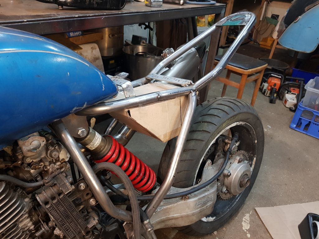
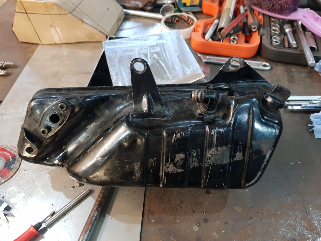
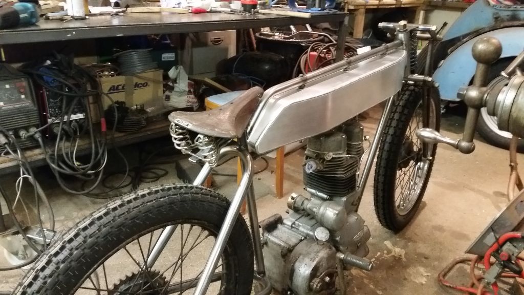
Dry sump so needs a tank FFS, not even thought about this, ordered an original from eBay to get me out of the doo-doo and it’s an ugly beast to say the least…, for some reason it does’nt fit perfectly with how I have changed the layout of the frame, back to the drawing board for me.
So, my thought are now I can make something that does not look so out of place, tucked up under the seat as best we can, space to mount the cdi on top and far enough away from the carbs not to get in the way when we build filters.
Time for some choppy choppy with cardboard and sticky tape, try to get a rough idea of how it might fit and try to get a similar volume or even a bit larger.
I’ve tried to work out volume and think this cardboard mock up is much bigger than it needs to be so I’ll chop it down a bit then make a metal version.
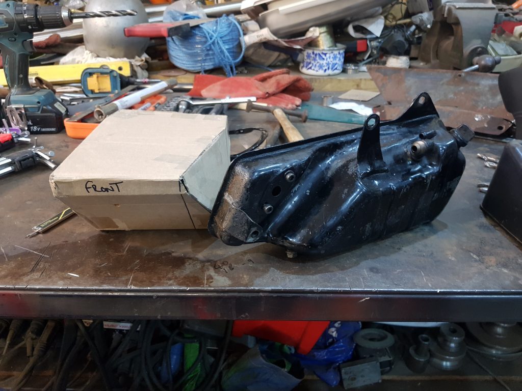
Looks a fair bit different to the original..
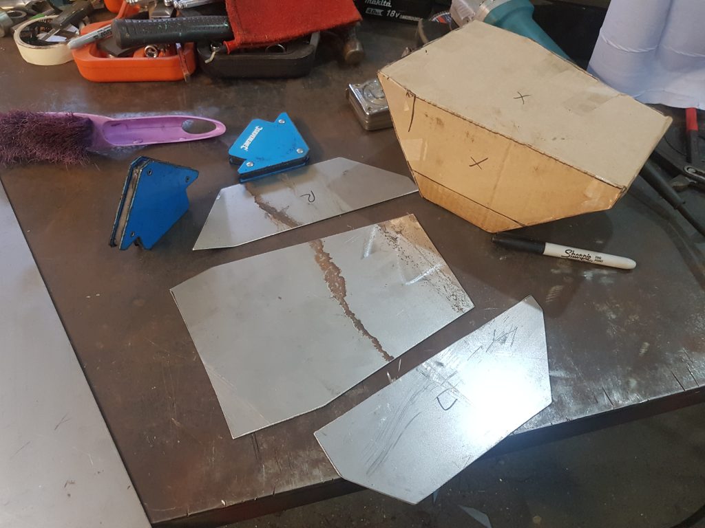
Draw around the box and transfer it to steel plate, I’m using 1.6mm as I have some in stock. I have reduced the size as per the line on the card box. Next we need to bend the plates prior to welding, we use a ‘state of the art’ bending machine to get exact bends.
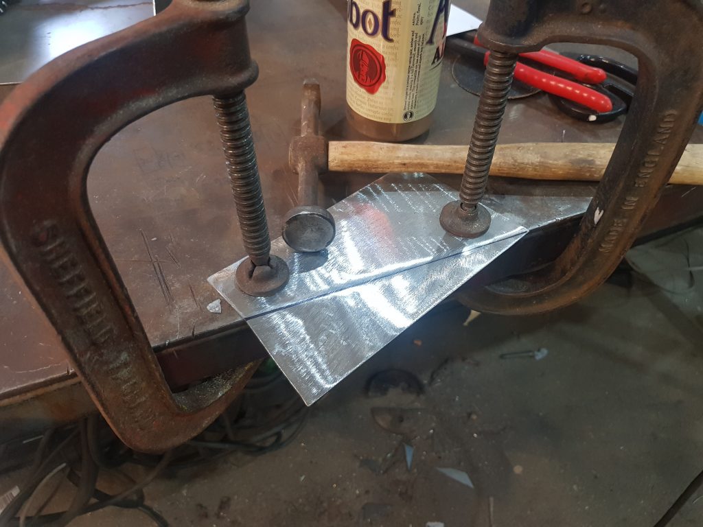
Ok, so the Scavengers have yet to get a bending machine so we just G-clamp stuff to the bench and whack it with a big hammer, similar results. Next we need to tack the parts together.
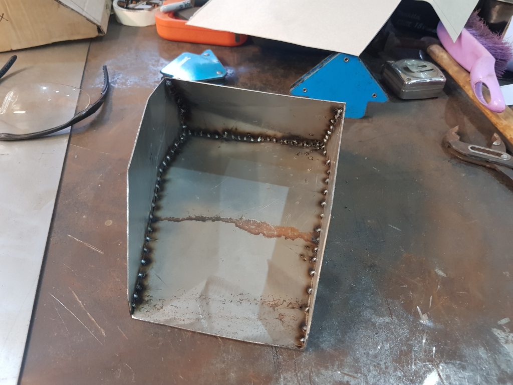
The plan is to tack on the inside with the mig welder as it’s quick and easy and when finished seam weld the outside with the tig welder to get an oil tight seal, failing that just get a really thick powder coat….JOKING
Finished up for the night and for some reason I shone my torch back in the workshop…WOW….I have been breathing this in all night, no wonder I get shed bogies.
Next job is to procure an oil feed fitting, the threaded elbow you can see, I am lucky enough to live near some racing companies that stock this sort of thing so this should be easy! OK, not so easy as it turns out, it’s not a standard pipe thread, it’s metric…grrr
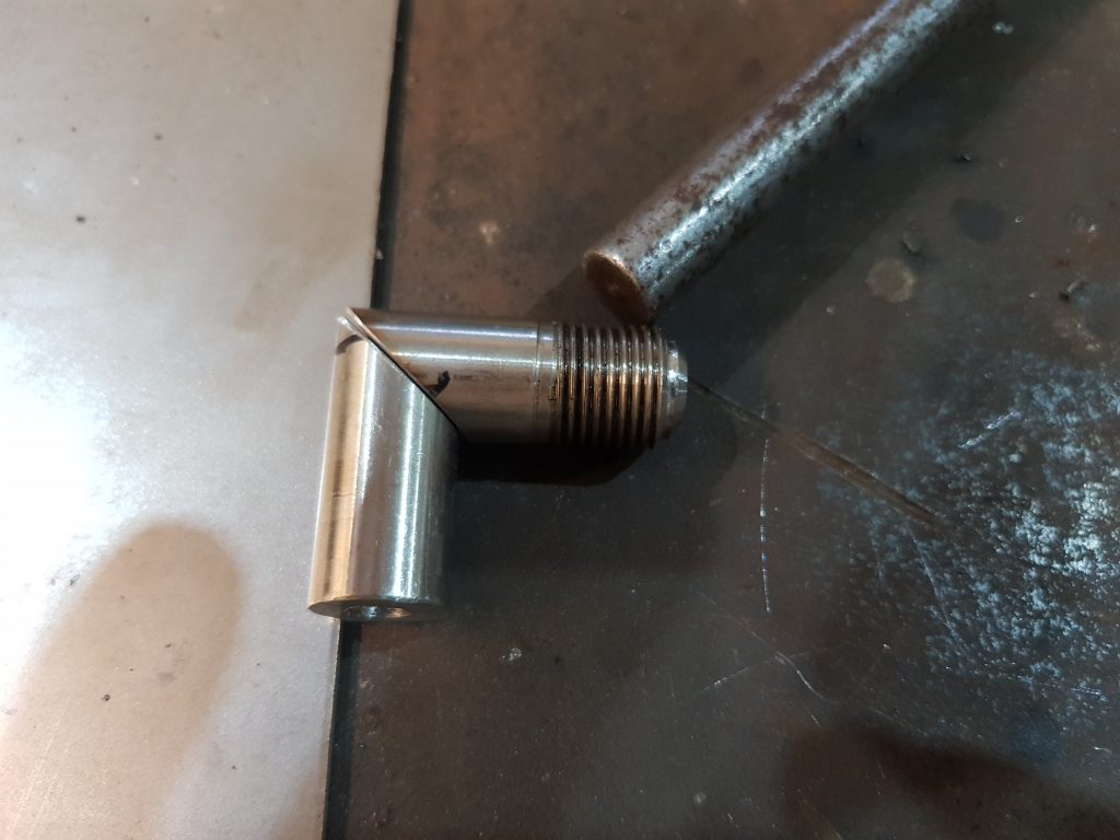
I’m loathed to cut up this tank just to get a fitting out and I’m struggling to buy one but… I have just found an M16x1.5 die in my drawer that I bought for some use on the XS project so I can now make one!!
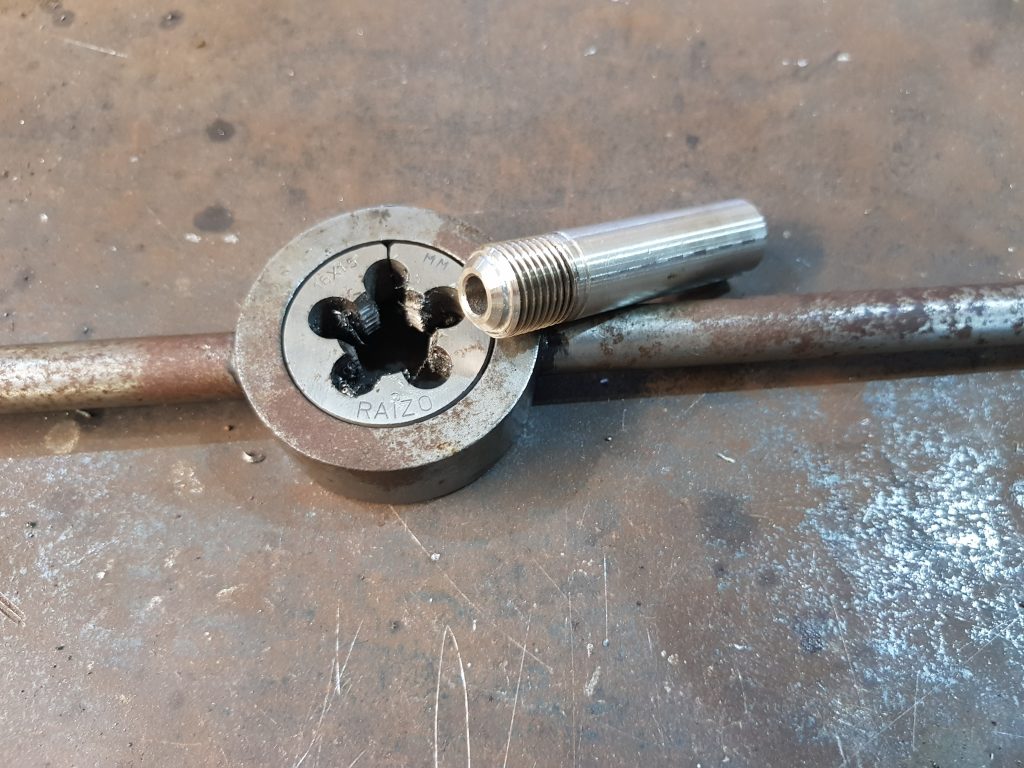
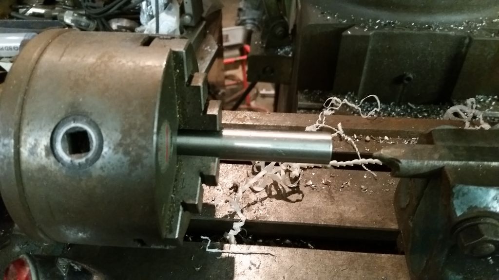
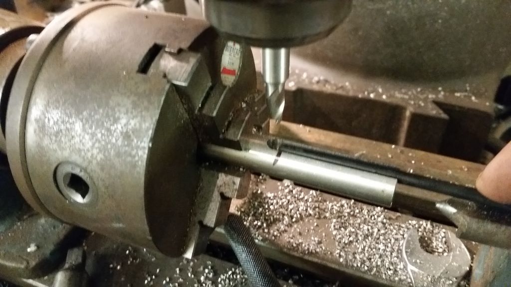
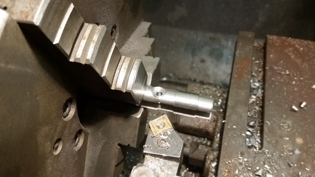
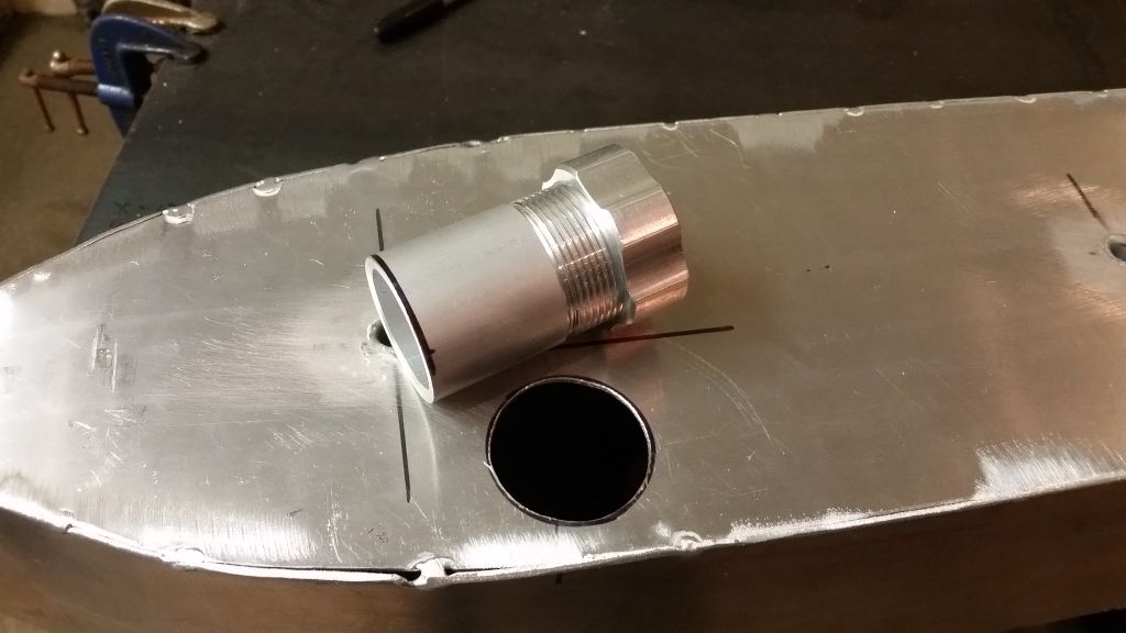
I have bored a 6mm hole all the way through and added the thread just need to make the 45 degree angle.
To make the cut I used the scavengers water jet cutting machine, the burn marks you see on the cut are from water and not where it was G-clamped to the bench and attacked with a grinder by eye in the hope the cut would be somewhere near where we needed it. Yee-Haw..
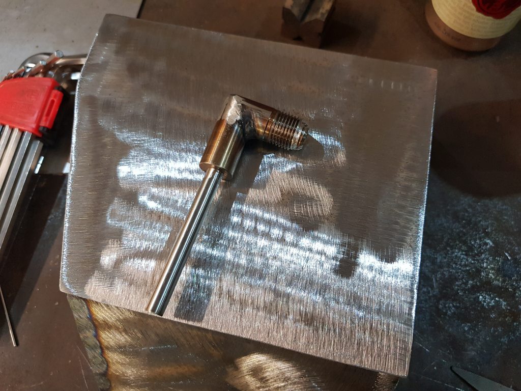
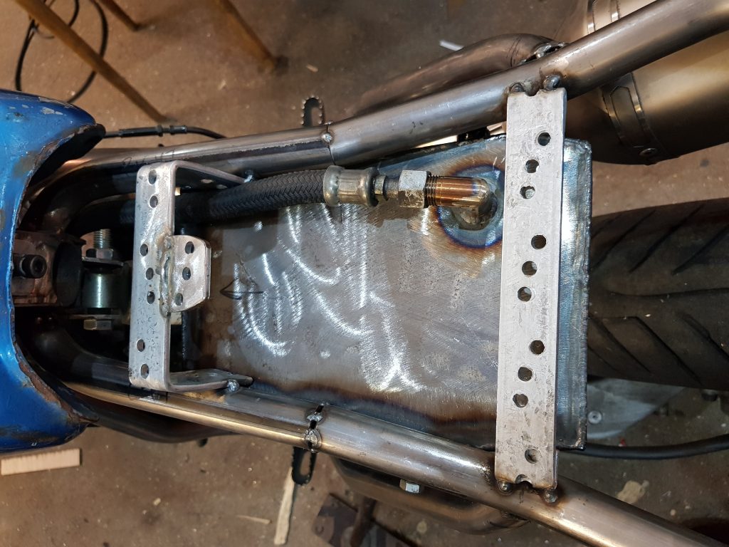
Once seam welded with the tig and ground off the excess bits it looks alright, need to weld this in place but I’m going to hang fire here a bit as there is some slack in the connecting pipe so I don’t need to commit just yet, I’ll wait untill the cdi is mounted and see how it looks.
Update….so I, for some drunken unknown reason decided to go ahead and weld the elbow in place exactly where it looked like it should go from the bench rather than on the bike….
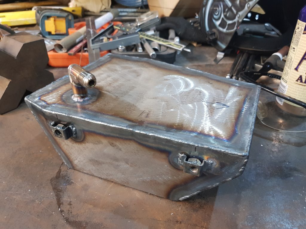
Looks alright, you can see the long weld closest to camera, this runs in line with the frame so even a stoned monkey could figure out when I add a fitting to the elbow it’s going to hit the bloody frame, one of those moments, all adds to experience though.
Interesting story/fact, when I went to night skool to learn about engineering one of the things that has stuck in my head over the years is something told to me by the tutor (Jack), ‘It’s not a problem making a mistake, it’s how you get out of it that counts.’ wise words from a very clever man.
There is not a lot of room but as it turns out a new 1mm slitting disc in the grinder can just about reach so I started to trim away the welds, went as deep as I dared and then used a large wrench to rotate the elbow to get it free.
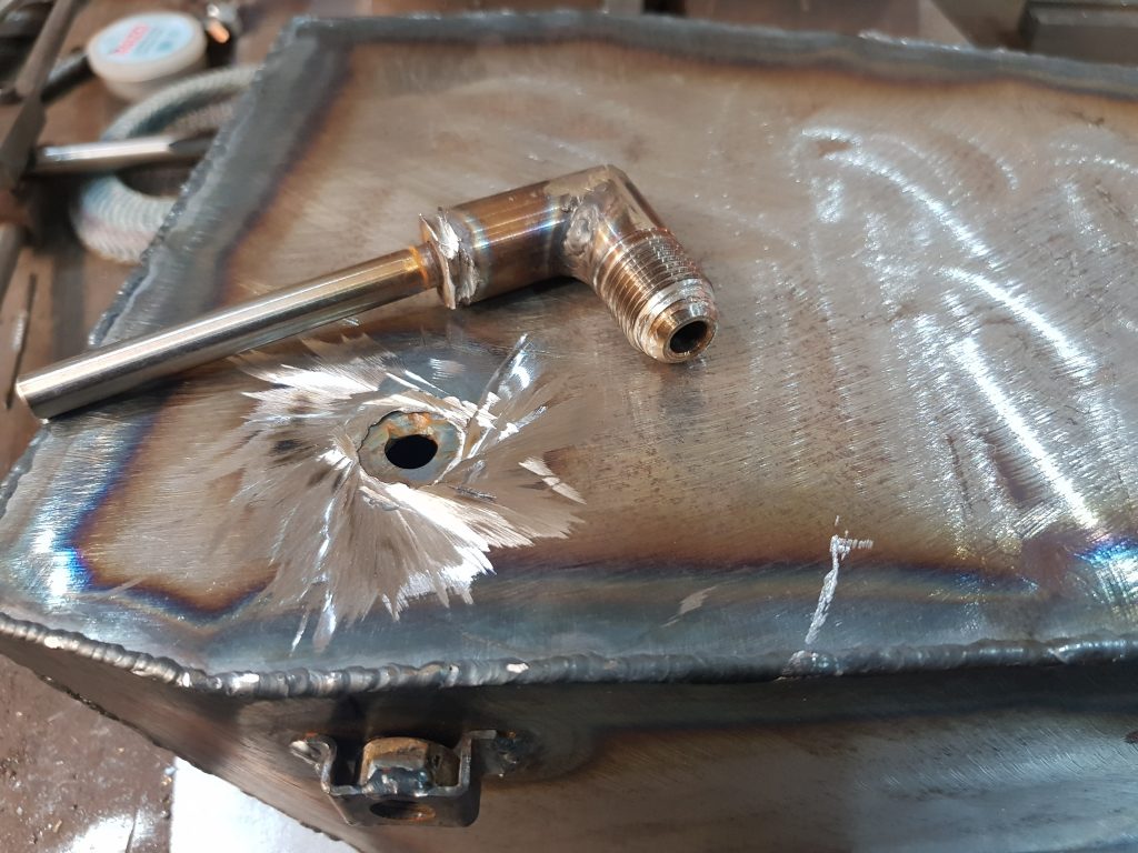
Bit of a mess but fixable, thats the beauty of welding, just keep poking in filler wire to cover up your mess!
So we have missed the frame this time, much better, now we need a way to fill the tank, had a rummage around and I’ve found an oil bung from a car, looks new!
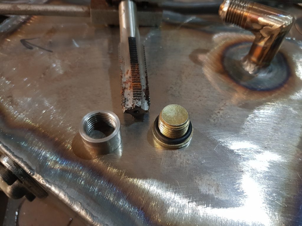
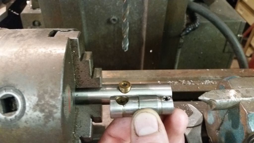
Found a rubber ring that fits and quickly whipped up a threaded jobbie on the lathe, turns out the thread is the same as the elbow so I already had a tap to suit, a little rusty but it worked fine.
I’ll weld it in place tomorrow, need to make some kind of drain plug then I can weld the bottom on the tank. I want to add a magnet to the drain plug as I think it’s a great way to get an early warning if something is letting go internaly.
I quite like making exhausts, I was given a crash course by ‘Wolfy’, friend of the Scavengers and an all round decent chap, very creative and tallented more than me, his work with stainless steel is world class but when it come to needlecraft or macrame I’m the boss OVER 60% of the time.
Unfortunately for me, stainless steel is the material of choice for exhausts, can be tricky to get in the size you want and the bends used must be formed using the mandrel proccess. I am in lockdown, mail order is very limited so I am aiming to use whatever I can get my grubby little mitts on, I have a few leftovers and managed to order some bends, it will be fine.
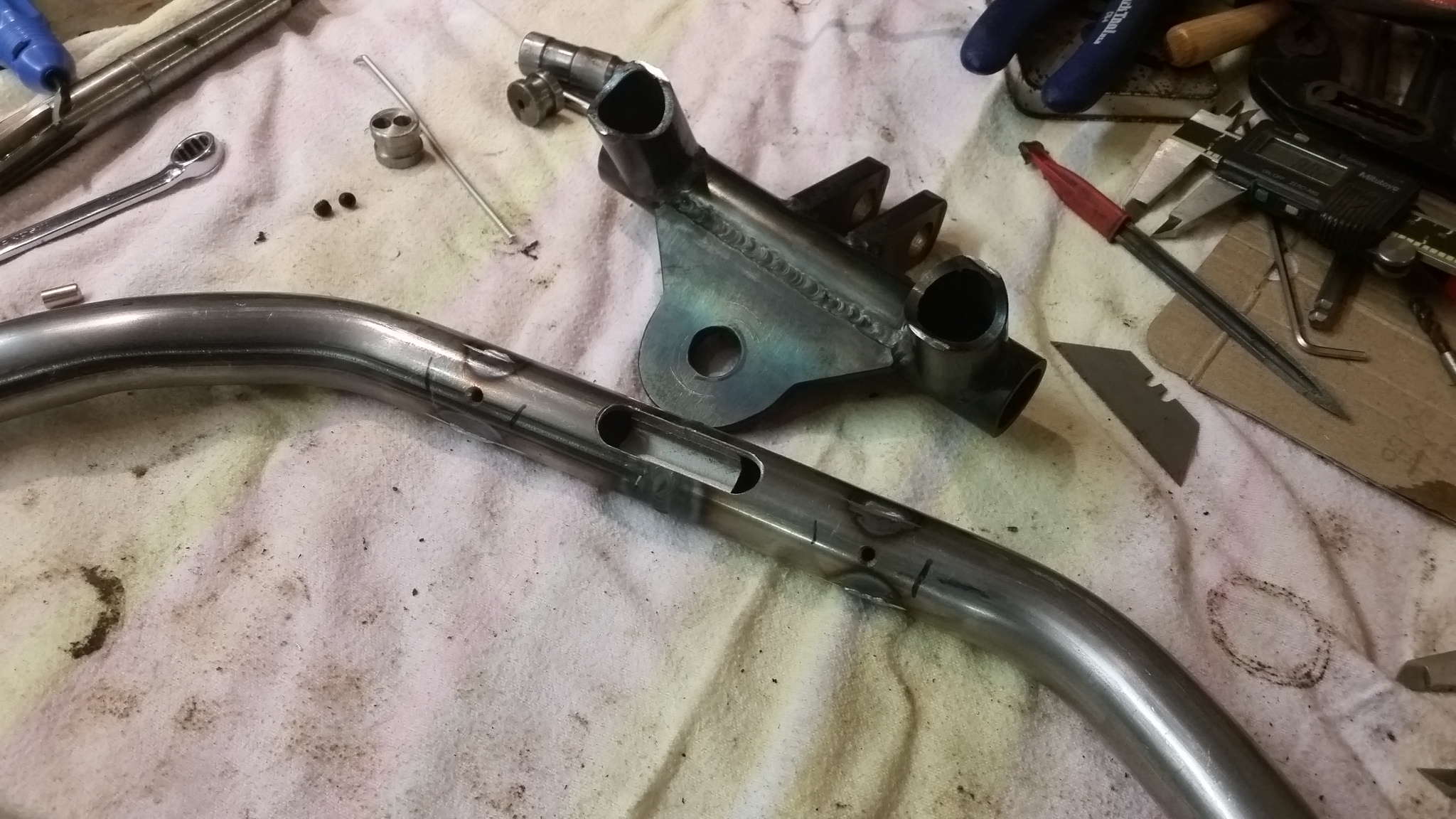
First things first, we need some flange’s, we, the Scavengers love a nice flange, not oversized or rough to look at, a nice tidy flange.
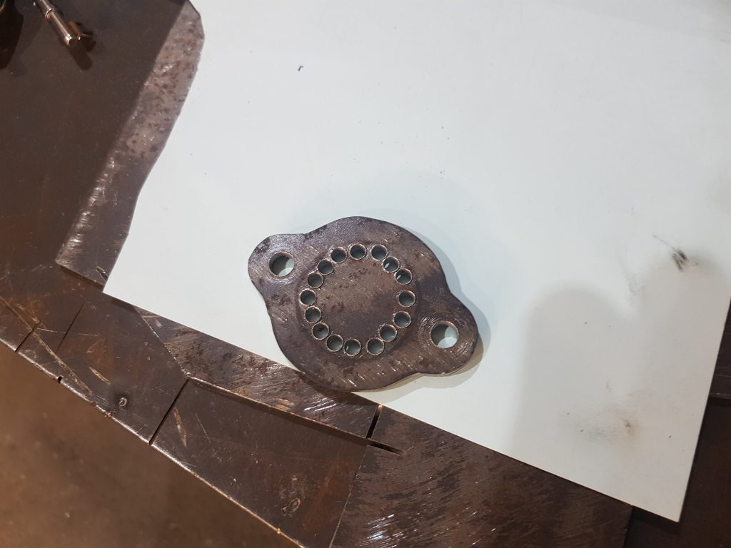
I dont have a way of cutting the middle out so chain drilling holes will do, you just drill in a circle and use a small chisel to join the holes then finish up with a file.
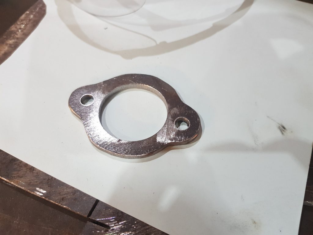
Thats not too bad, I made a pair as for some reason this single cyliner engine needs to outlets.. Could have got a pair of these en eBay for 16 quid but thats not our way!
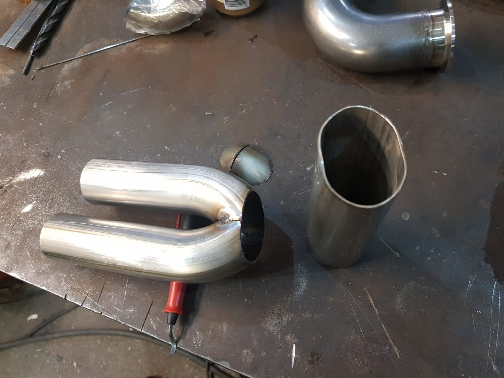
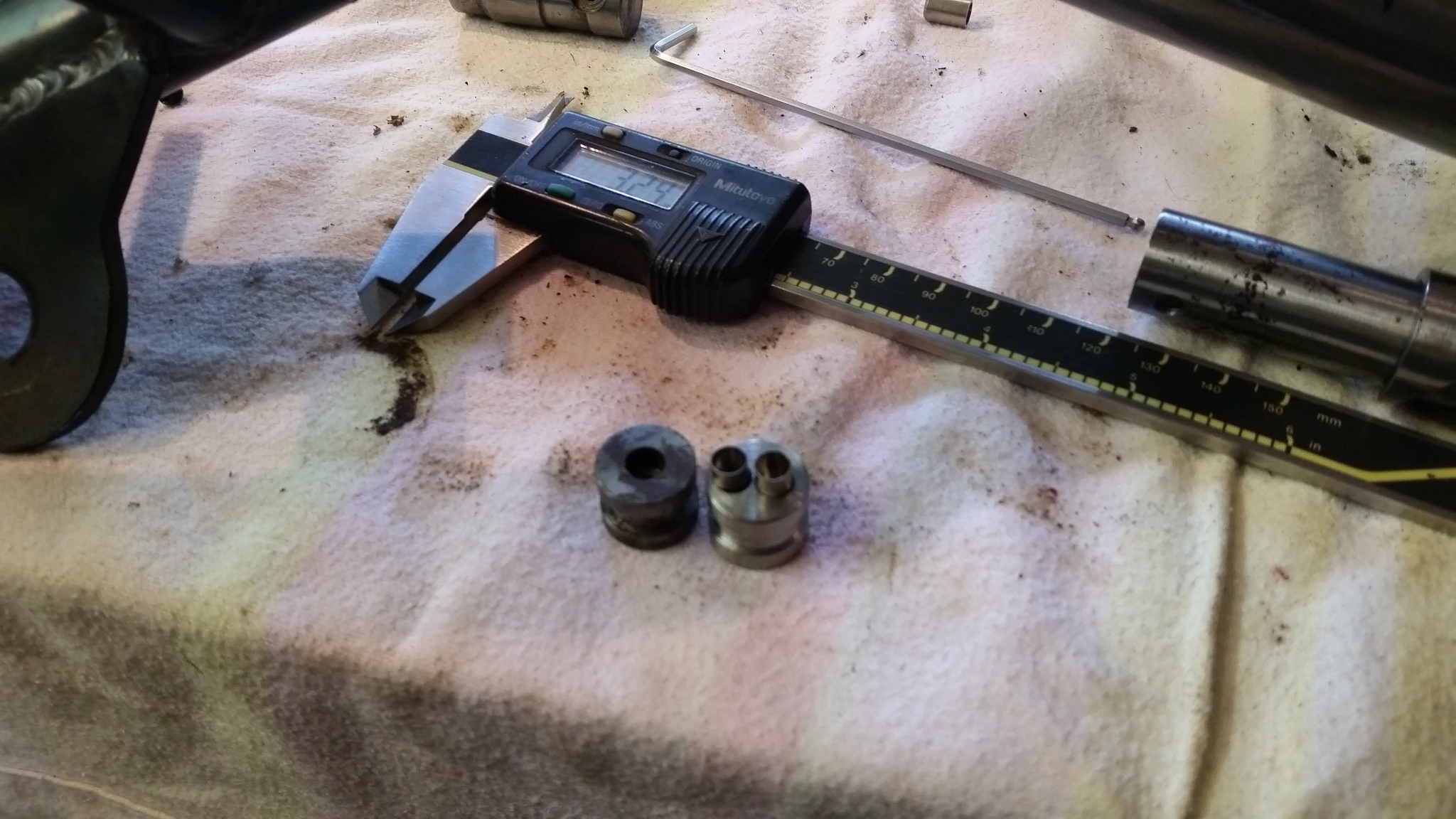
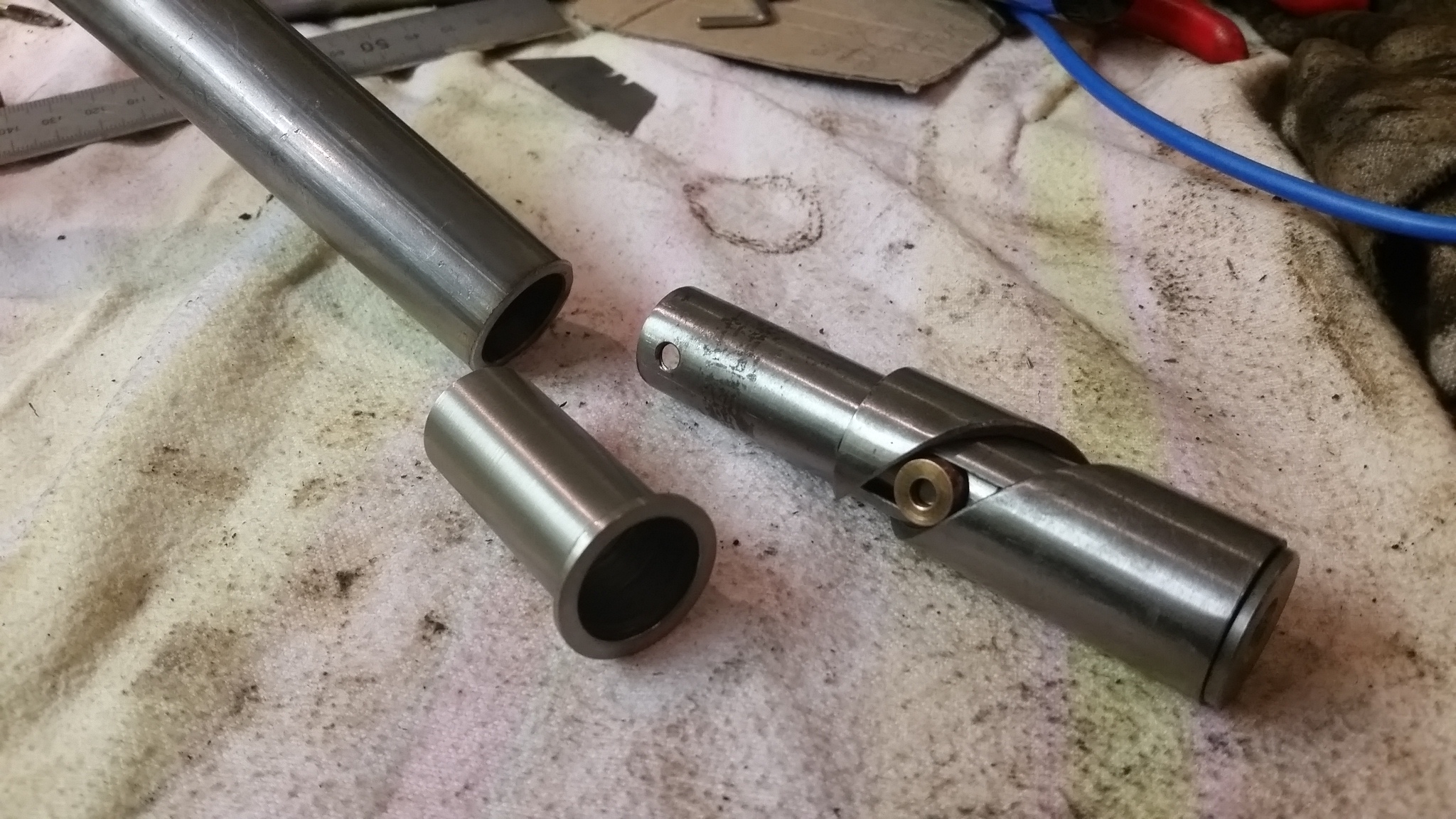
Next I need to work out how to make a tidy job of bringing together the two pipes in to one, I need to buy something so I bought a 180 degree bend.
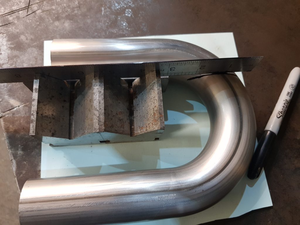
This cost eleven quid delivered. I used a spacer to stand away from the pipe, you can see this under the ruler and balenced it against some blocks to keep it straight, marked with a sharpie and started cutting.
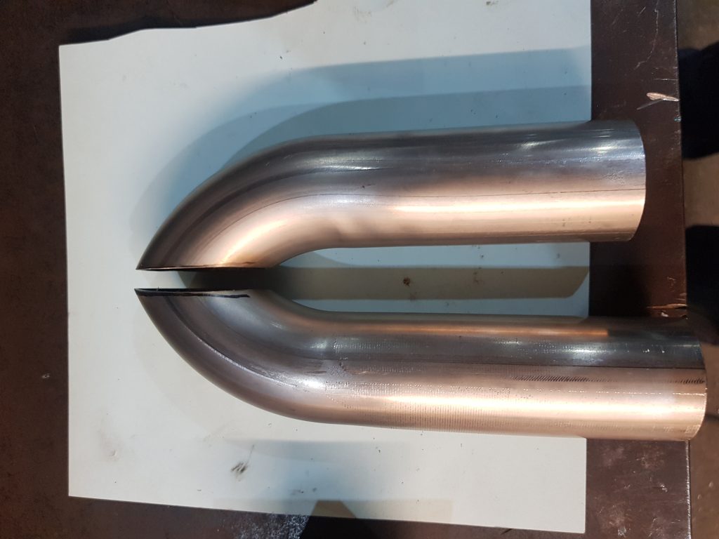
I can now weld these together to make a collector, these are a bigger size than the tube I will use to come from the manifold, they slip together nicely, time to get a move on with the manifolds.
Added the first parts, can’t go too far wrong here as long as they dont foul each other.
That all fits ok, slips nicely in to the collector we made earlier.
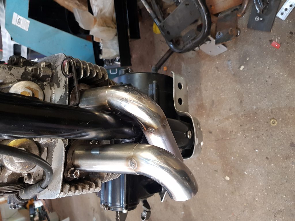
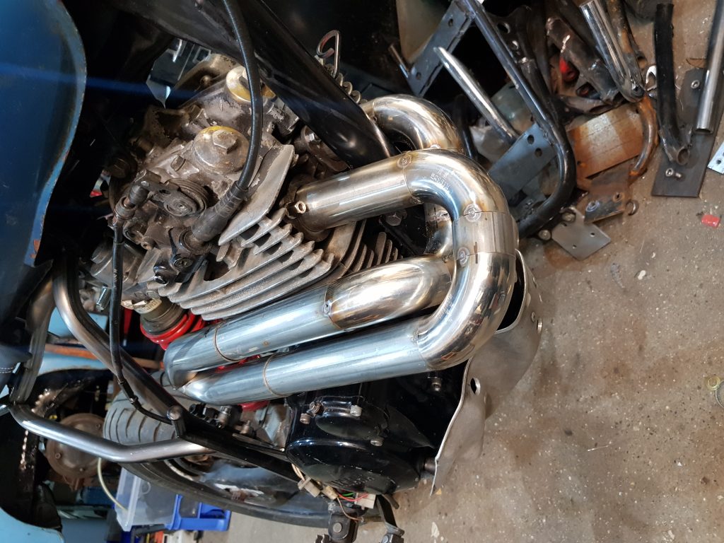
Needed to bring the 2″ pipe down to 38mm so I just squashed it in the vice, lined it up on the collector and drew round it then took the grinder to it and hey presto they did’nt fit, spent ages tinkering with my grinder to get a good fit but got there in the end.
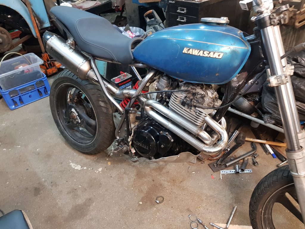
There were a couple of other bends to play with to route it around the frame but you get the gist of it, none of it matches but I’m not bothered. Check out the sexy end can, it’s from a superduke 1290, it came from Mac’s Harley project and was very easy to unbolt whilst my daughter distracted him by throwing rocks at the front of his house.
I don’t have a seat kicking around and don’t feel like making one, I will at some point but not this time, I’ll check out eBay and see whats going like a budgie…cheep.
Loads to choose from, quite like some of the Chinese offerings but the flattish ones are all geared up to look like cafe racer style, what I would really like is something similar to an MTX50 seat, flat and rides over the tank by a few inches, very simple.
I have looked at too many seats and I’m getting bored, I’ll just get something I like the look of and worry about how to blend it with the tank later, my choice is from a 2016 Yamaha Tracer 700, taken from a showroom bike, 35 quid delivered and it’s mint.
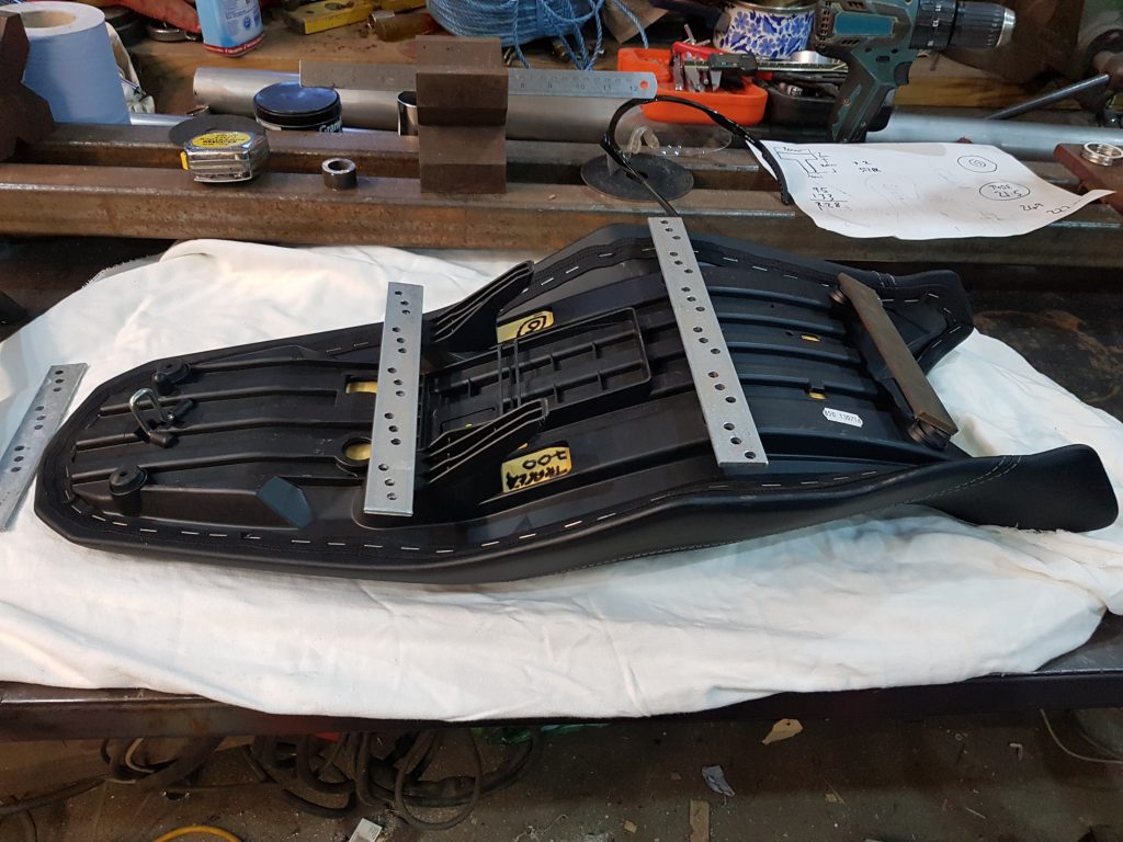
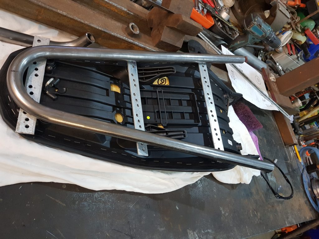
There it is in all it’s glory, I have roughly cut a few cross braces from some left overs from a guttering job I did for my mum, thats all I could find, this gives me some idea of how to make a sub-frame.
I bent a length of tube very simply just to see where to go with this, starting to look like a fit.
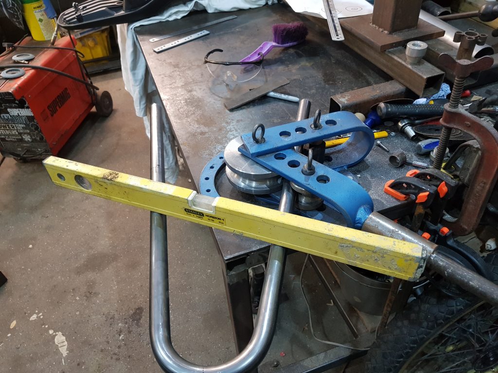
A few tweaks on the bender and it’s starting to take shape!
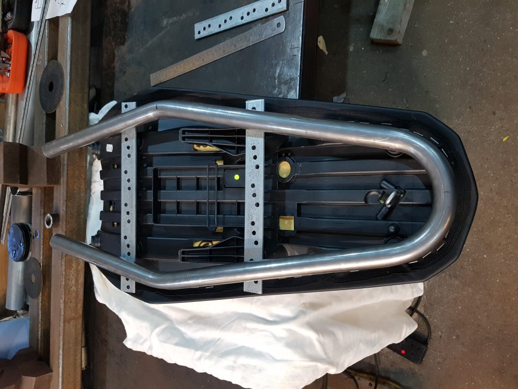
Looks pretty tidy.
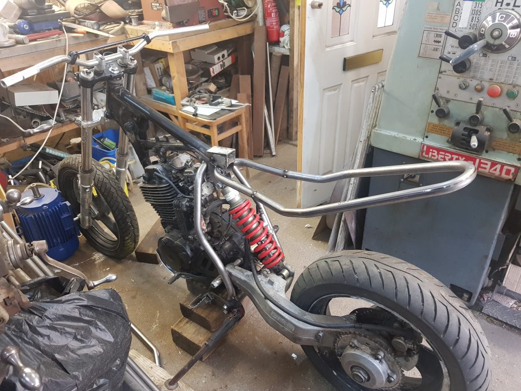
There it sit’s, I used some engineering string attached to the centre of the handle bars and lined that up with the centre of the rear tyre so I could eye up where to weld the subrame, the technology we use is mind blowing.
Starting to look alright, need to make another brace for the right side, feels odd to make the braces differently but this is the first single sided swing arm bike I have built.
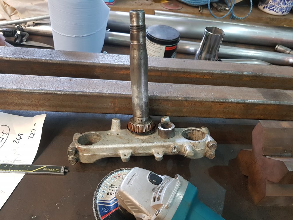
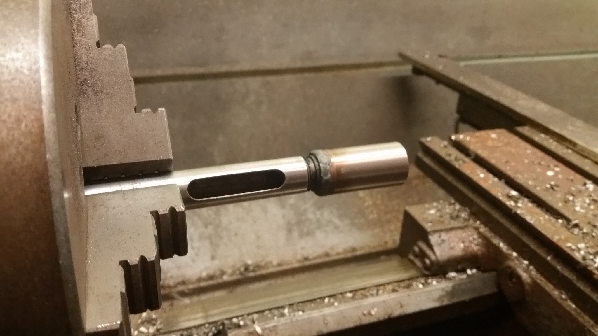
Been busily not doing much in the lock down, like most folk I guess, tinkering in the garden and more importantly doing a few bits to the XT project…. OOOHHH exciting I hear you cry! So, it’s about time I got this thing standing on it’s own two feet, I purchased a set of yokes on eBay from Legend-biking, they went missing as things do from time to time but I was sent a replacement set so I could continue, different year bike but I decided it would probably be ok, my mistake.. seems like the later models have a longer head stock tube, by about an inch so the newly arrived yokes wont fit…..ok I’ll chop a bit out of them and make these ones fit!
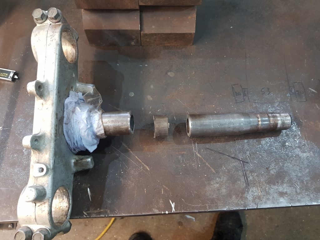
Before you say it, no I could’nt just wind down the nut further, the upper bearing is smaller so would not reach as the shaft widens. We, the Scavengers pride ourselves on our wide shafts and exposed nuts, rumour has it Mac’s nuts are CHROMED, I cry like a girly when I get caught by a stinging nettle so I’ll stick with my nuts as they are, standard.
There you go, a nice big straight shaft with a pot of lube in the background and a GRINDER…what the hell is happening!!!! I thought we were family friendly…..
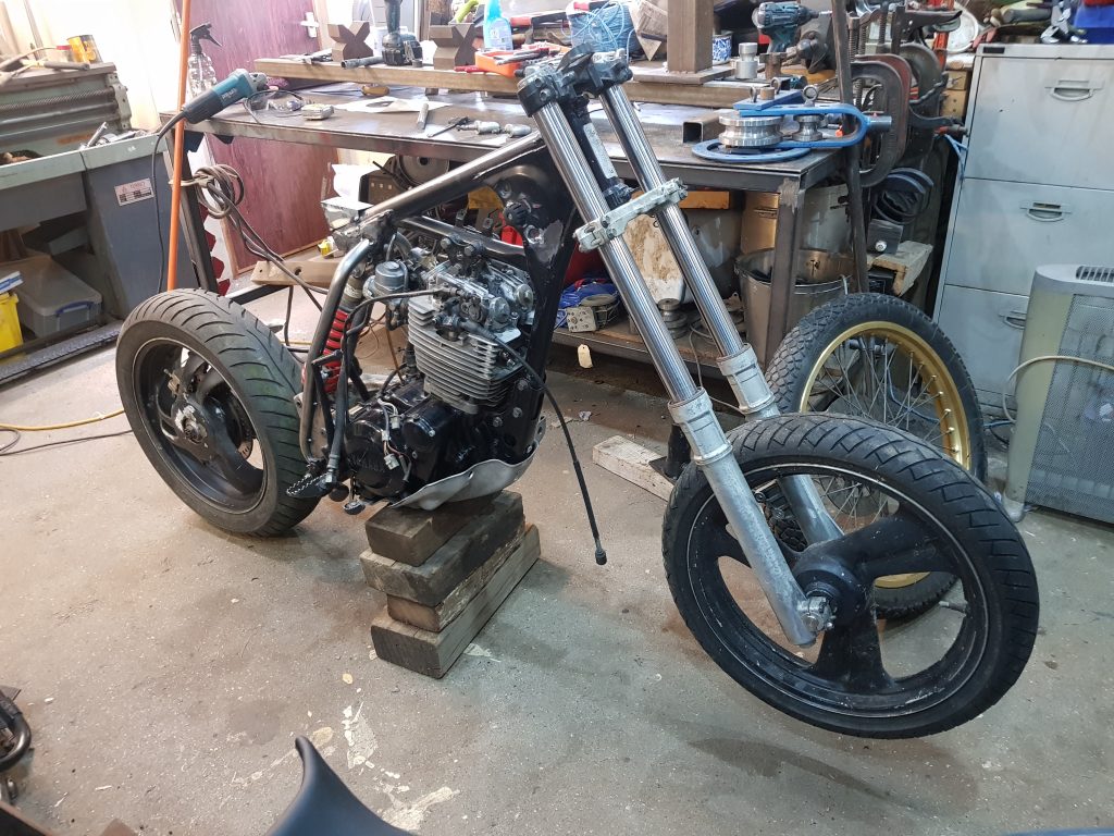
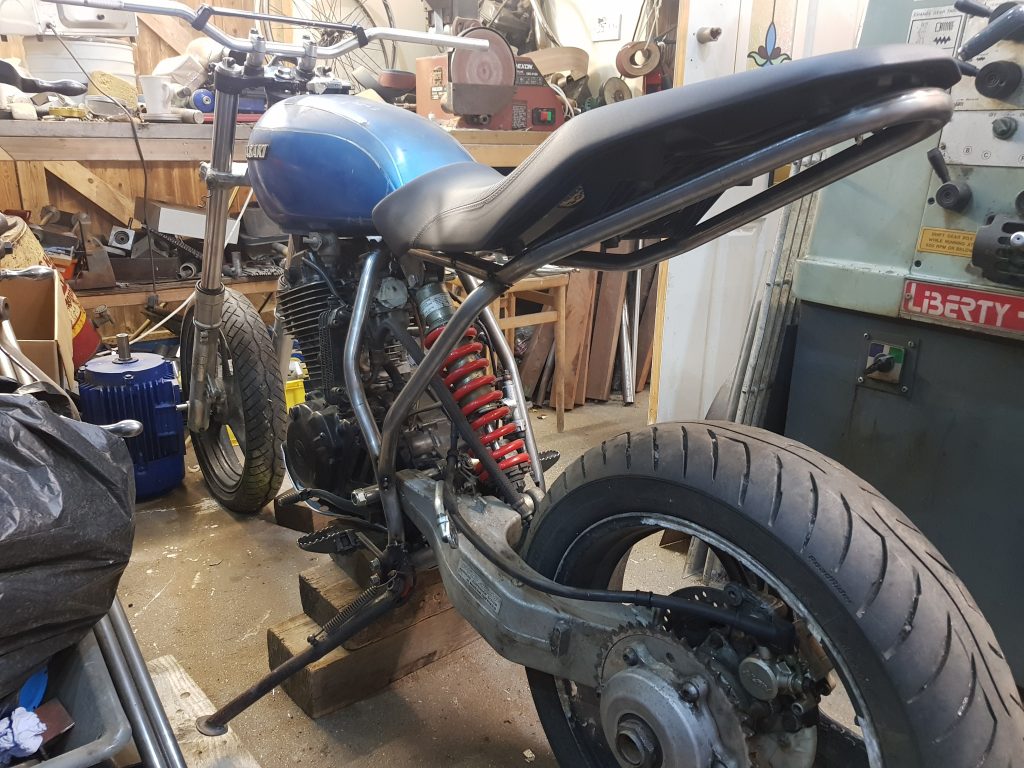
Pretty happy, the front end is working as it should at this stage, time for me to give the back end a seeing too…..TEE HEE HEE…., honestly, a couple of beers and this place is going to ruin..
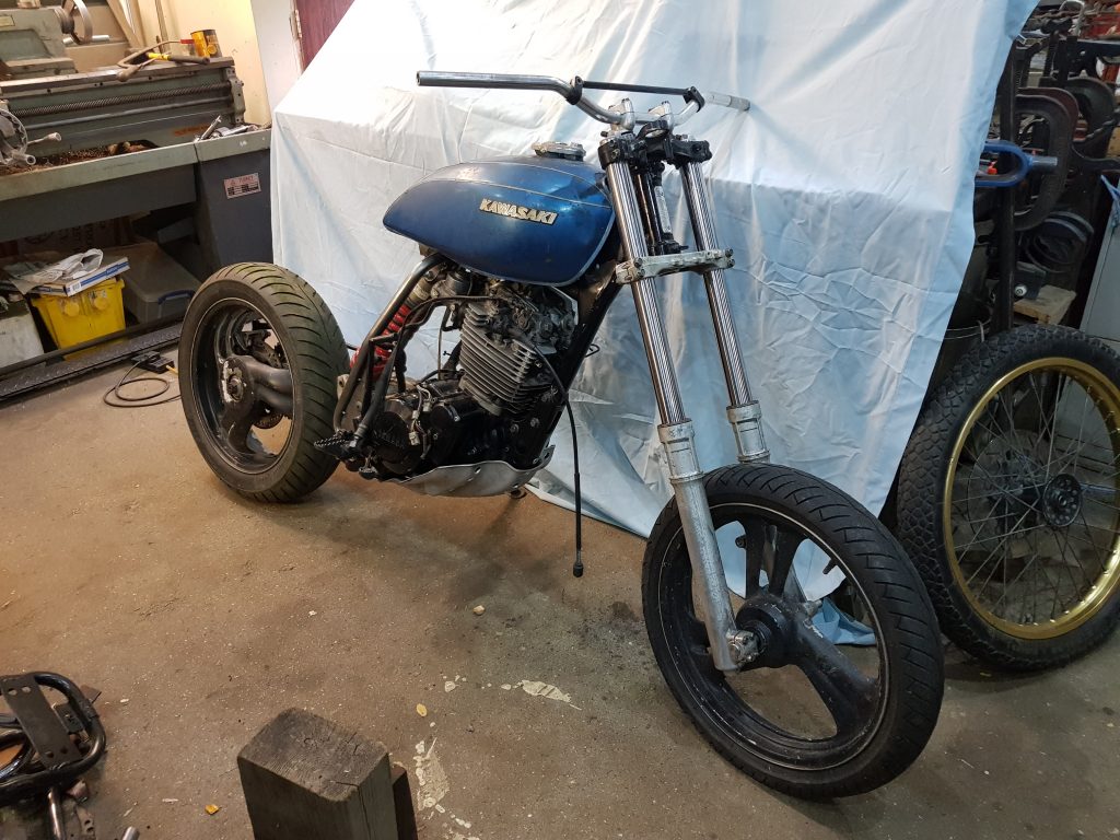
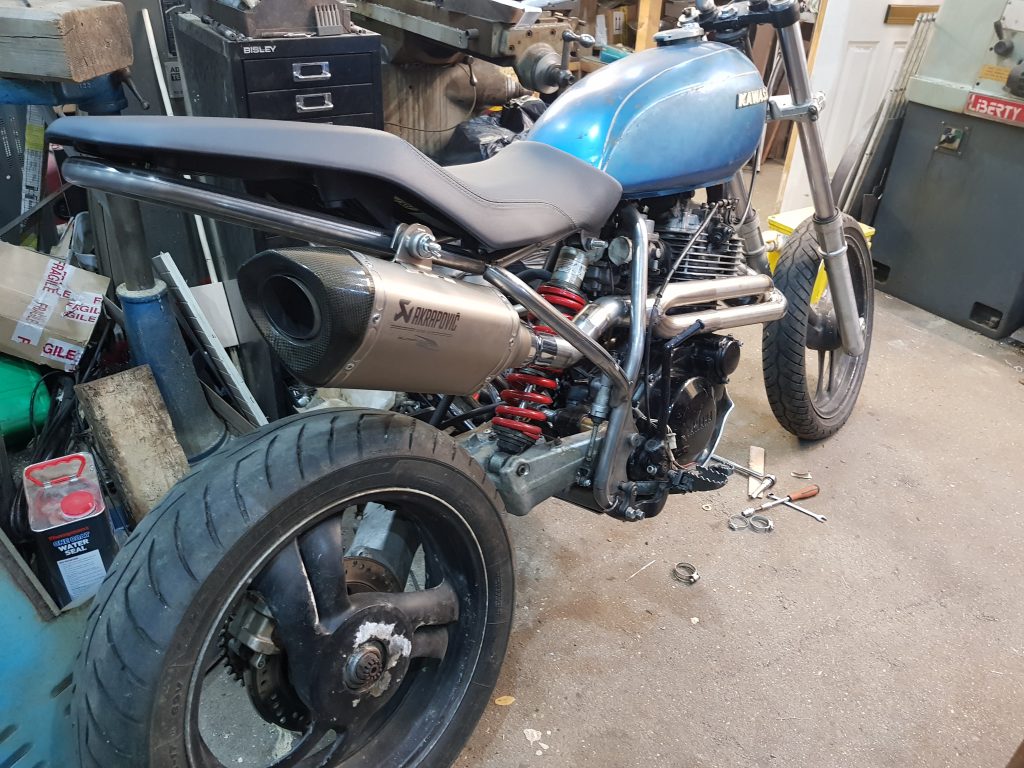
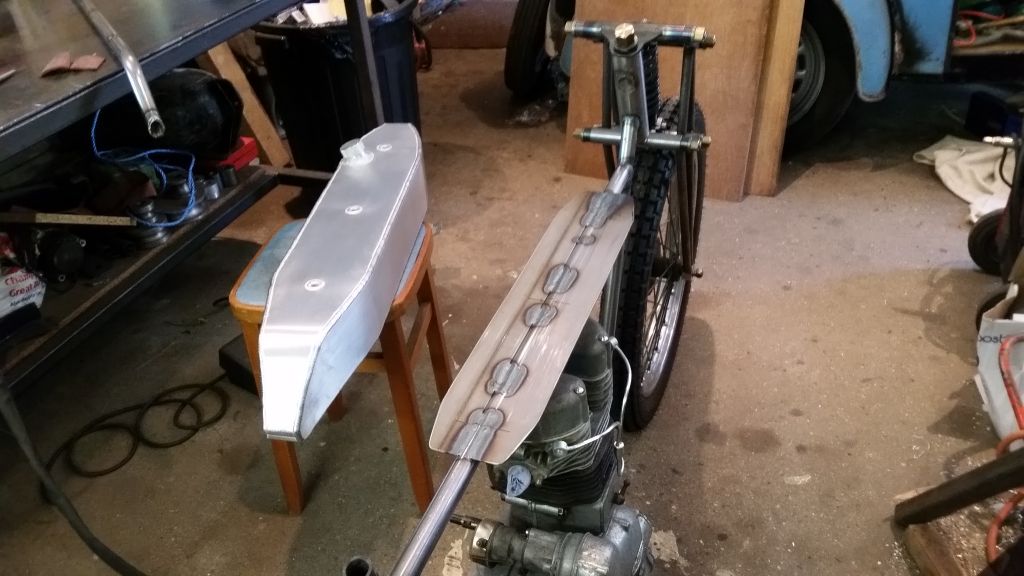
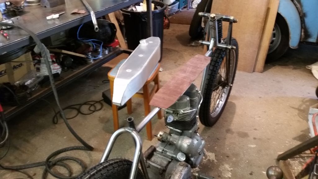
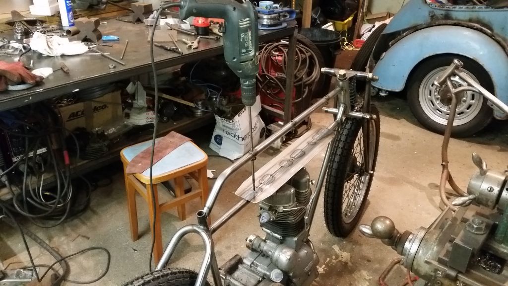
Here’s a sneaky peak so you can see what direction I’m heading in, Z400 tank from ’75 and straight’ish handle bars that I failed to return from the Last job I did for Mac, the tank cost me 35 quid plus postage on eBay, it does not fit well but is the shape I want so it’s staying, the seat is from 2016 and is an even worse fit but thats staying too, I really like it…just need to blend it all together, it’ll be fine, I have a plan!!
So, sometime ago whilst chewing the fat with Mac, probably half cut, there was talk of maybe starting a new project, this time I wanted to do something different. It must have suspension this time as my back is aging quicker than me, something comfy, cool to look at (do we even say cool anymore or was that an 80’s thing I forgot to drop..? man..) and more of an off-road twist
There was a sniff of a project coming available from an old friend of Mac’s, quite a reliable chap that doesn’t ask the earth for anything either, the details were vague but we knew it was a big single pot trail bike from the 80’s, mostly complete and with a log book! That ticks all the boxes I need but I was pretty skint at the time so had to back out although I was really keen.
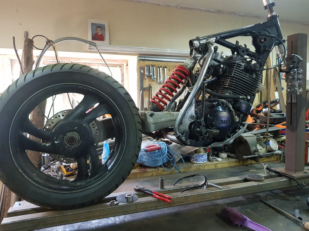
Sometime later whilst perusing Mac’s vast warehouse of motorcycle madness he took me to a dark corner on one of the lower floors, took a key from around his neck and opened a small side door and lead me in to the ‘New projects store room’ There it was, a Yammy XT600, well most of it, the good bits! A few months later when finances were easier it was mine! Thank you ‘Bank of Mac’, very much appreciated.
There is an engine, forks, front wheel and a box of bits also, quite a few bits missing but the way I’m seeing it is they were parts that would have been replaced anyway. A previous owner has had a go at changing the look of the bike by removing the tail section to remodel it, I think they were going for a cafe racer style but that’s not what I’m doing so I’ll just chop it off.
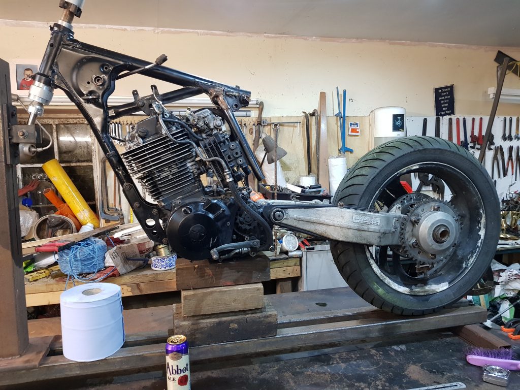
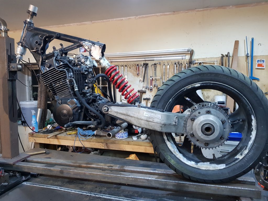
I should point out this is a couple of weeks in to Covid 19 lockdown so getting hold of parts will be tricky but not as tricky as getting hold of bogroll for some unknown reason.. Rumour has it Mac knows a man, he can get Andrex triple ply, it’s not what you know.. A quick slice later and the cafe racer mod is gone, engine/swing arm are bolted in, I don’t have a back wheel…I’ll have a look around my parts to see what might fit.
I could not find a normal back wheel but I found a back wheel in a single sided swing arm from a Honda Bros 400 also from the 80’s or 90’s..? It does not even close to fit, it’s wider and offset and does not sit central, might as well be from a different bike. I am going to need to remove more frame to get this to fit.
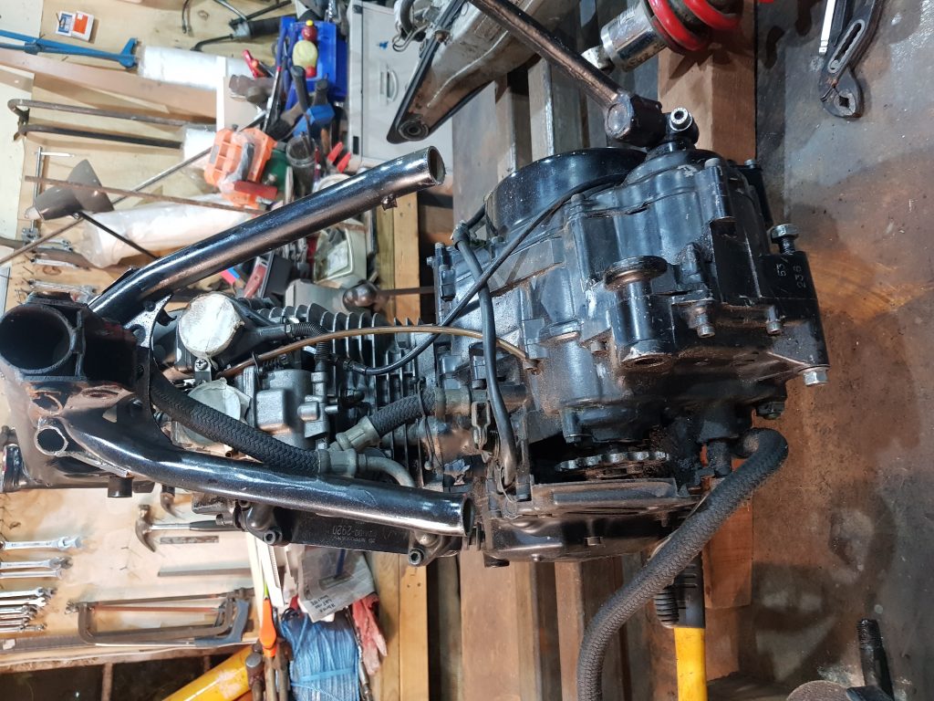
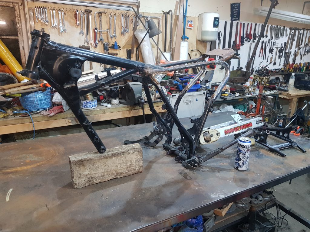
So I have removed more frame, I’m sure I’m going to lose both of these down tubes completely but I’m leaving them there for now. Time to try a fit with the swing arm and see just how far out we are..
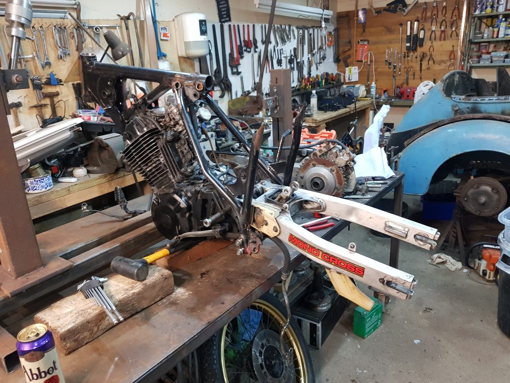
That looks hopeful, the swing arm spindle is the right size, it fits through the back of the engine fine and I can make the frame to suit, time to try the suspension unit for ride height.
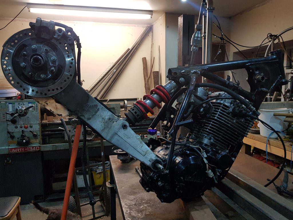
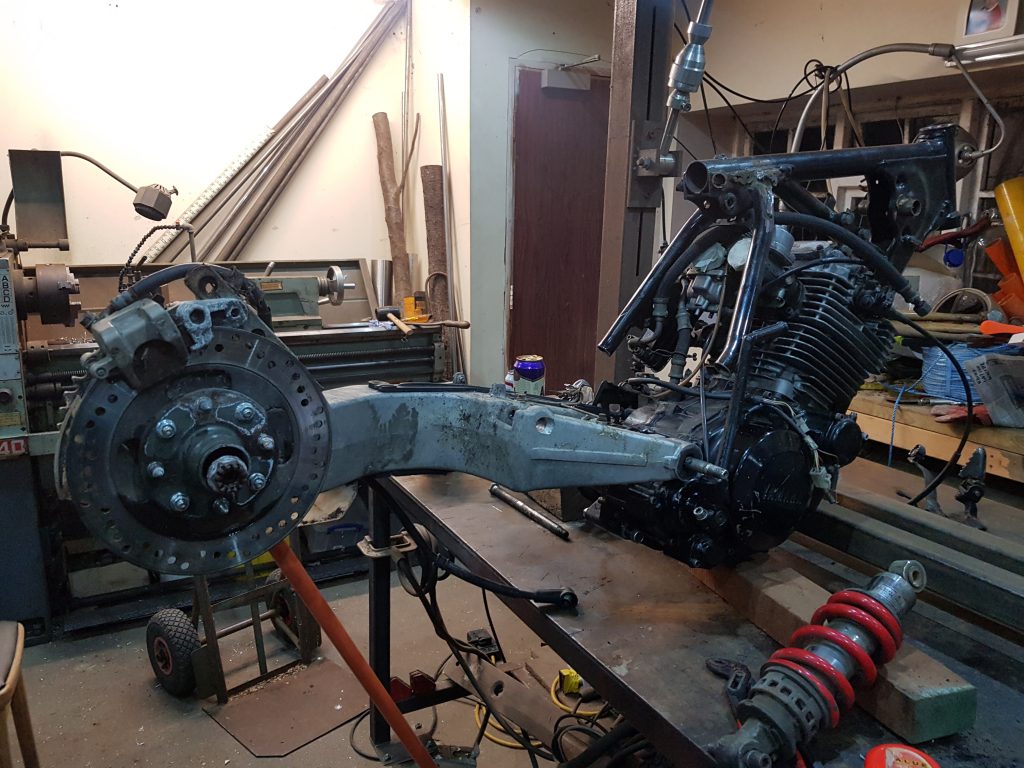
Now I’m not a pro at this game but I’m pretty sure the rear wheel needs to be lower than the handle bars so I suspect the suspension unit either needs to be longer or drasticly move the top mount, I’ll phone Mac and see what he has in stock.
Turns out Mac has ordered the house staff (not allowed to call them servants) to draw him a body temperature bath of goats milk and has ordered 12 punkah wallah’s to circle him whilst he watches close up images of Harley Davidsons on his 50 inch flat screen held by 2 Telly wallah’s, so no he cant answer the phone right now so I’ll move on to spacing the swing arm instead.
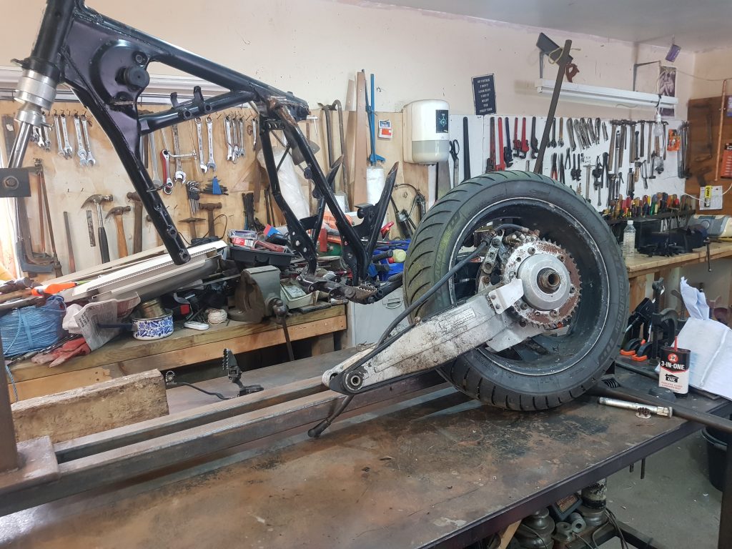
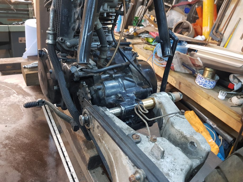
One of the issues I’m having is the offset between the centre of the bike relevant to the drive chain, if I move the swing arm to a place where the sprockets line up it means the rear wheel will track 18mm to the right so it is no longer following the front wheel, ideally I want the rear wheel to track exactly behing the front and I want the sprockets to line up, I forgot to get a picture of this but if you bolt the sprocket on the wrong side of the carrier and make a 5mm spacer to go between the carrier and the bearing it’s close enough, just make spacers to suit the swing arm at the pivot and we are getting closer!
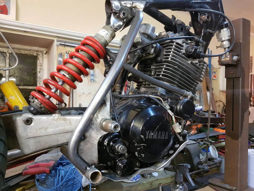
Now I have the sprockets and both wheels in line I’ll jack it up on the jig I made (£40) and work out how the new frame will accomodate the mounting points for both swing arm and foot pegs.
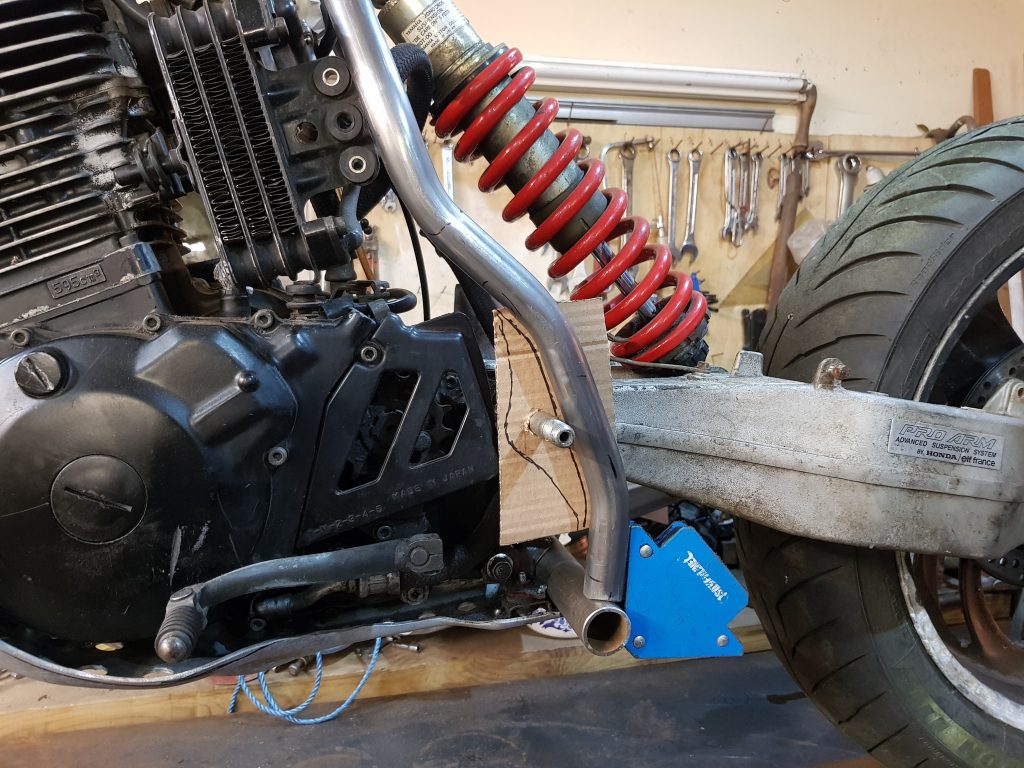
As you can see here the bottom mount/footpeg hanger is no where near wide enough, if I join a tube here it would foul the swing arm, see centre screen, this should be a one inch tube housing a gusset that accepts the swing arm mount and then attaching to the spine. (big frame tube under the tank) This needs to be at least 25mm wider, maybe more..?
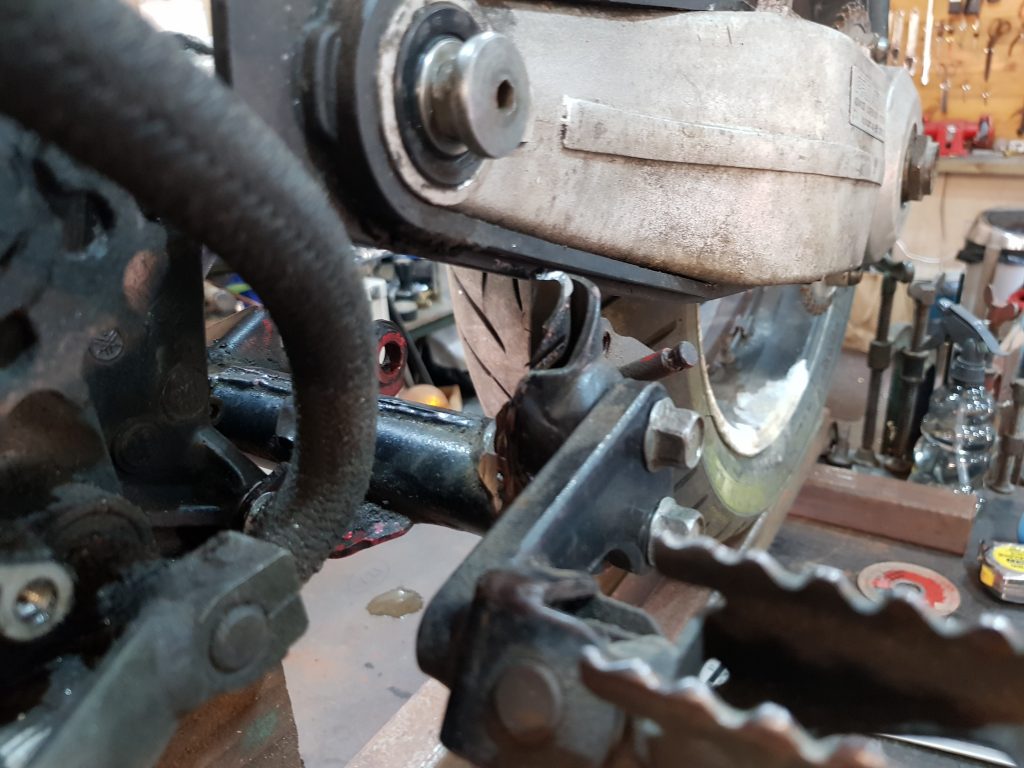
I need enough sticking out either side to attach the frame to the spine, it’s just not enough.
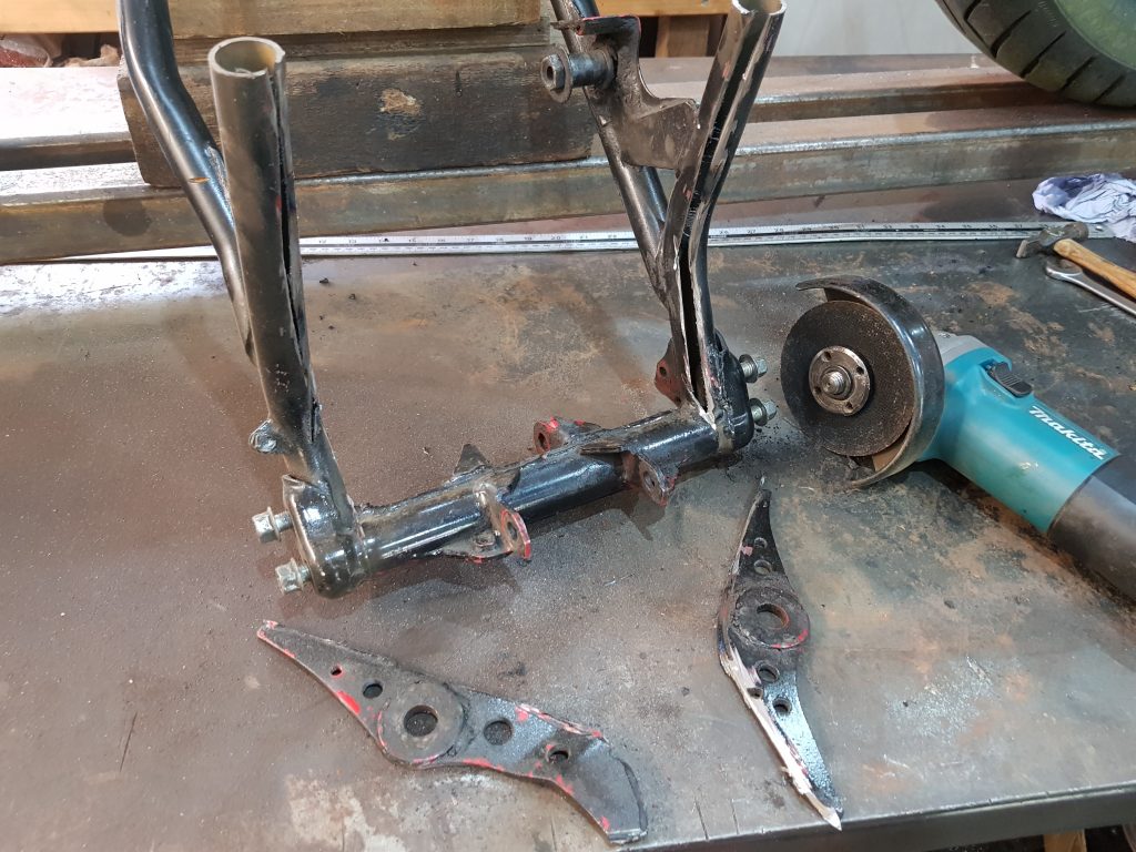
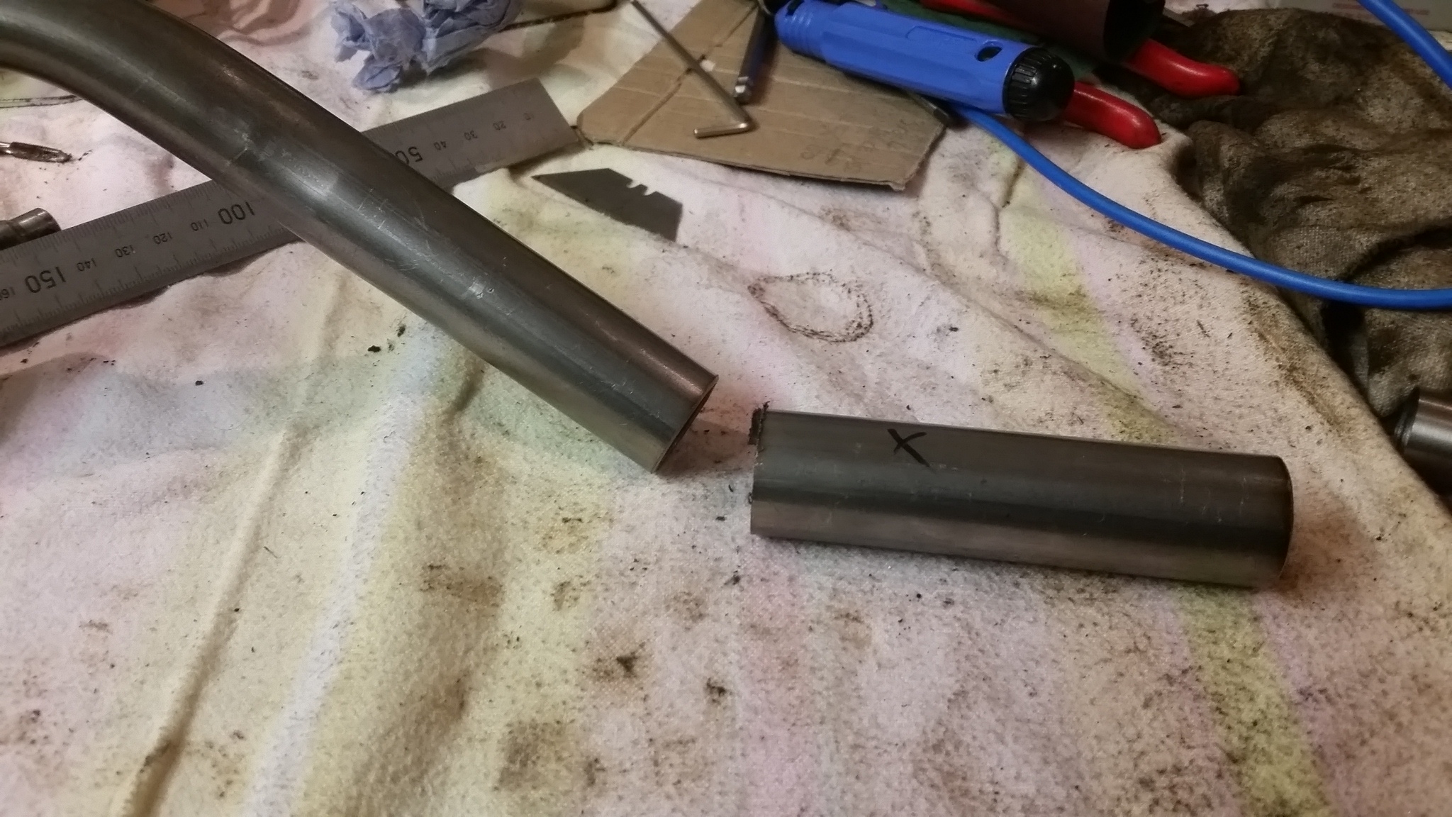
I’m not going to be able to make much use out of this, I could cut and extend it but that seems a bit of a bodge, I have an idea!
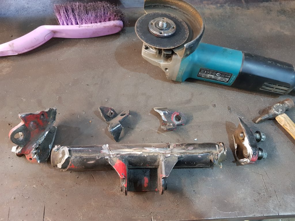
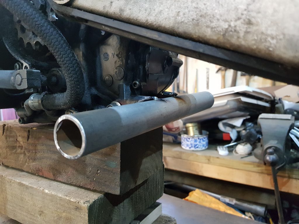
I’ll cut off the mounts and footpeg hangers, I’ve got some 32mm cold drawn tube from an earlier build so I’ll make a new’un.
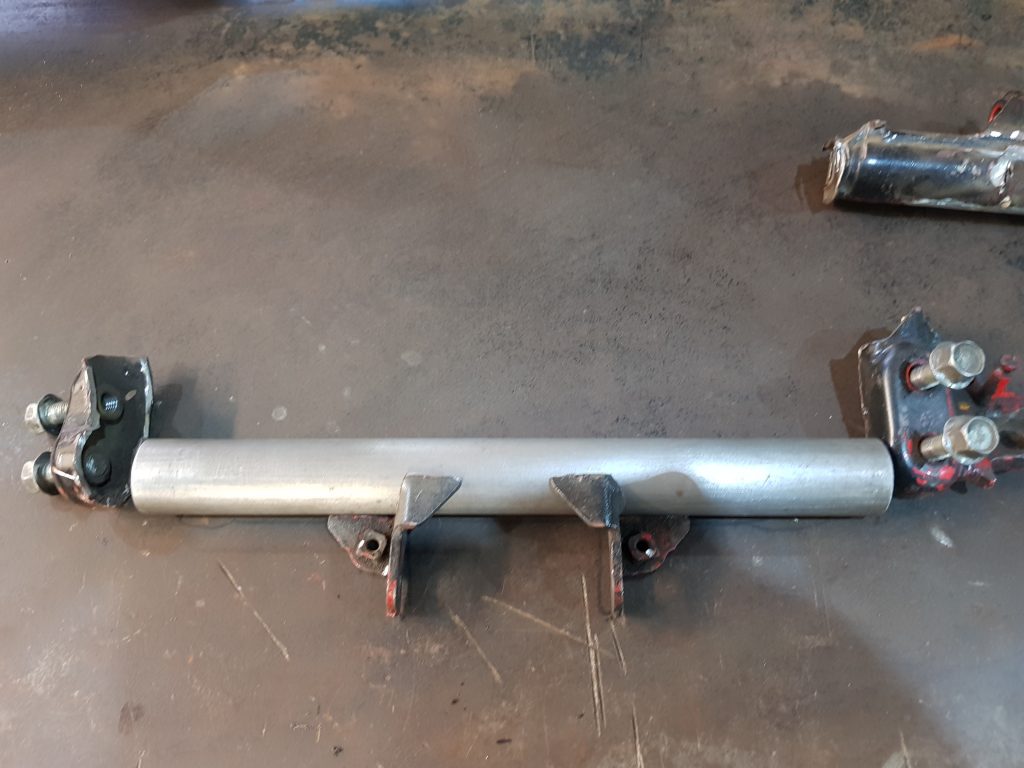
I’m going to play it clever and make the tube an over an inch too long on each end so I can concentrate on making the swing arm and frame mounts, plenty left over to stick the foot pegs on with, well thats the plan.
There we have it, the tube is now tacked to the mounts and is in place but I have just realised I need to switch back to mounting the rear shock absorber as any alteration I make up top will affect how much room I have to mount these up tubes from the swing arm, Mac had at some point finished his milk bath and dropped off a longer shocker but it’s still to short!
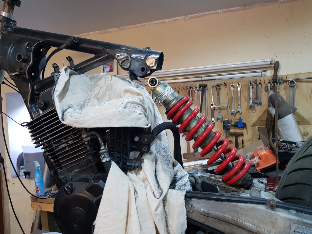
The bottom mount needed a bush making as the original bolt from the Bros was too skinny, easy fix. The top mount is entirely a guess and may need changing, I chose this possition for what looks a good ride height but as I don’t have a front end yet one could argue my calculations, I’ll try this and if it’s wrong I’ll fix it.
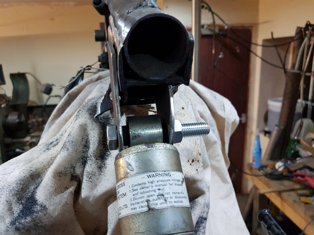
The bottom mount on the single sided swing arm is off set to the left a bit, the top mount on the bike is in the middle so I have moved it around to suit, looks wrong but it needs to be like this. This unit used to run with rockers on the bottom mount but is now going to be mounted direct so maybe to stiff to use like this, we will see.
Next job is to make the up tubes and join the bottom mount through the swing arm mount to the spine, lots of bends, I’m using inch tube with 1/8th wall and making the bends with my ebay bender (£270), it bends with brute force and a little luck.. (I bought plenty of tube to play with).
So there you have it! First side done and tacked in place including a gusset, these are very tricky to make and the skill takes years to master.
Or you could rip a bit off a box and draw round the tube with a sharpie, like I do.
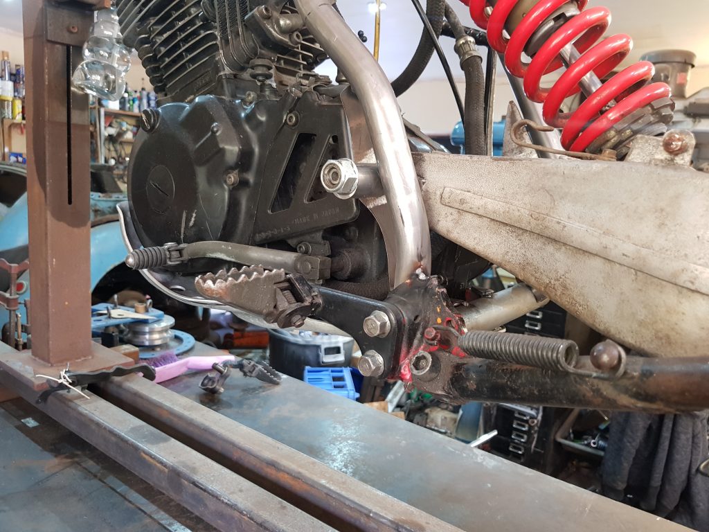
Footpeg mount tacked back in place, also mounts the stand.
Also mounted is the right footpeg, this is also mixed up with the rear brake, it was drum braked but now I have a disc so this is pushed to the back burner for now, I have bought a second hand master cylinder/pot from a xl650 Transalp, I took some measurements and worked out this was the cheapest one I could find so it would be a good fit. As it happens Mac has a contact not far away that makes hoses and are happy to play silly buggers so I’ll let them worry about the plumbing.
Tonight a little slice of history was made, OK when I say little I may be blowing things out of proportion a touch, never the less the Enfield has taken it’s first breath of 14/1 for a great deal of time, I don’t know when it was last started but I’ll make an educated guess that this was laid up 30+ years ago maybe a lot more, who knows.
I’ve been tinkering with this trying to get it started for a week or so but no joy, just a few pop’s and bangs to keep me interested, the clock is ticking and the Brackley bike show is now only a month away so I asked for a little help from Cooper, he’s a pain in the arse really, he has the midas touch…. just as I expected after me trying for a week he got it going in 5 minutes, bigger battery to make a better spark and force more fuel in to the carb as it’s not filling correctly, few kicks and off she went, back in to life after a very long sleep.
Need to make up a racing exhaust now…
Well.., popped round to Mac’s tonight to borrow a cable making kit for my new internal throttle, trying to keep the cables well tucked away this time.
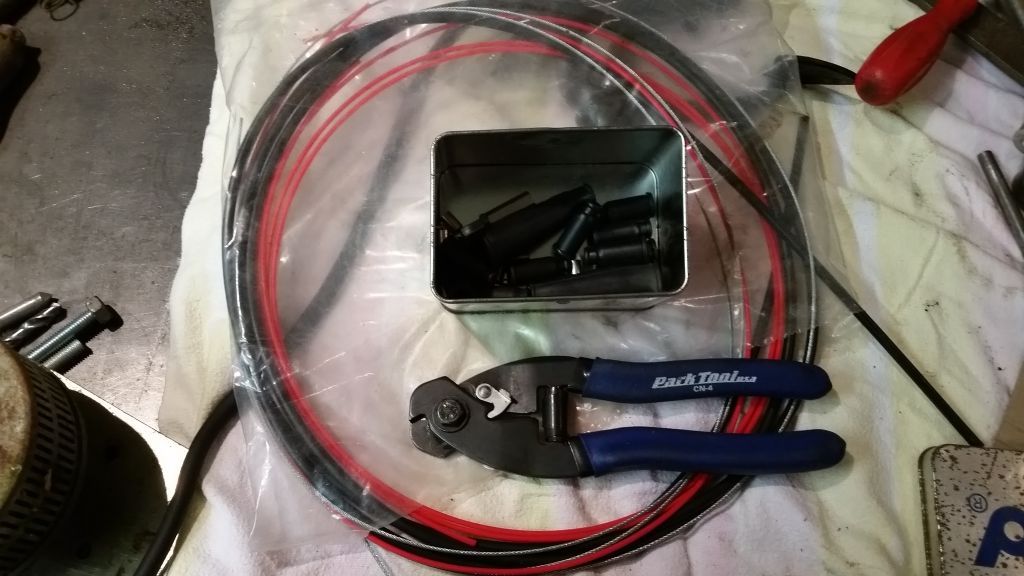
I should probably stop fannying about with such luxuries but I like the idea of a clean front end, I would like inverted levers too but I have hit a little snag, you can’t have both as the cables need to run the same path….Bugger…. So what now, a quick Google and the forums are saying the same thing, you can’t have both although there is a company called Cooke engineering that will make you the kit for the princely sum of 600 bucks, that’s 600 more than I am willing to pay so I need another solution, quite a bit of head scratching later I have a rough plan, I’ll just offset the cable for the throttle and run the brake to the side, i realise it will need to be inside the outer or we will get snags so lets crack on.
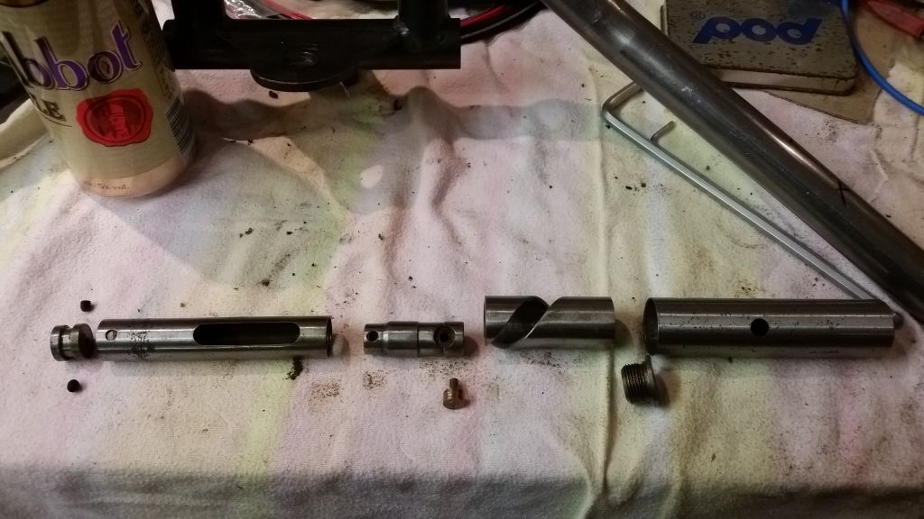
This is the internal assembly as I got it.
The problem part is the slider, well and both end plugs but they are easy to fix, you can see the cable we need to hide inside this part without interfering with the normal oporation of the slider.
Make a new one is the answer.
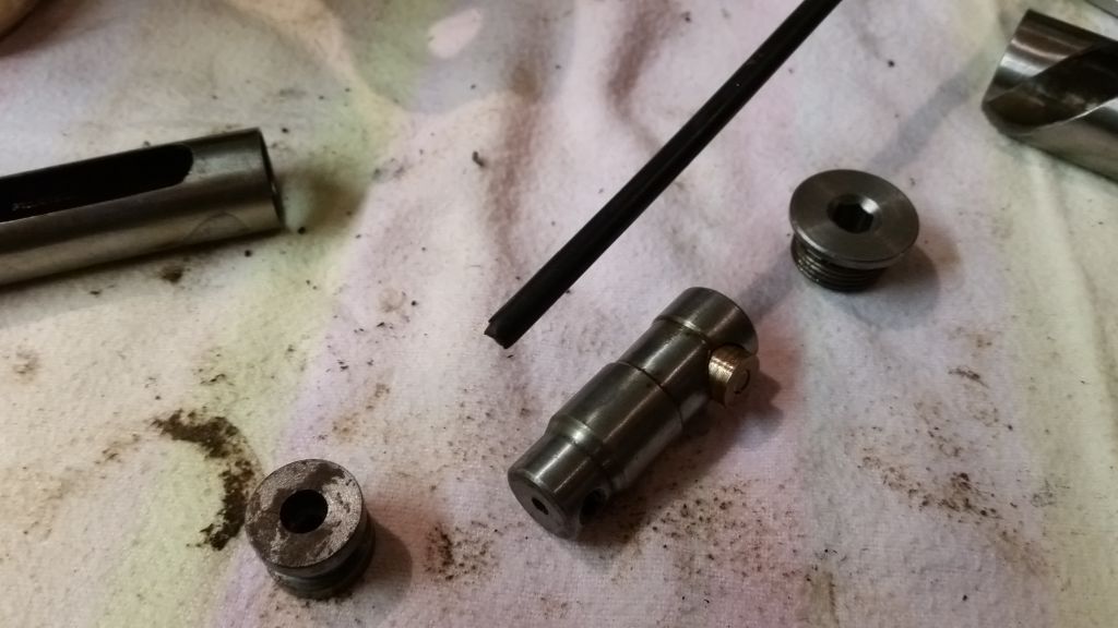
I drilled a 4mm hole for the pin and a 10mm pocked for the roller.
Added a slot to hide the cable, quite a bit bigger than the cable so I can add a lot of grease, any snagging here will be felt in the throttle.
Pop it in the lathe and make relief cuts to keep the friction down, keep it simple.
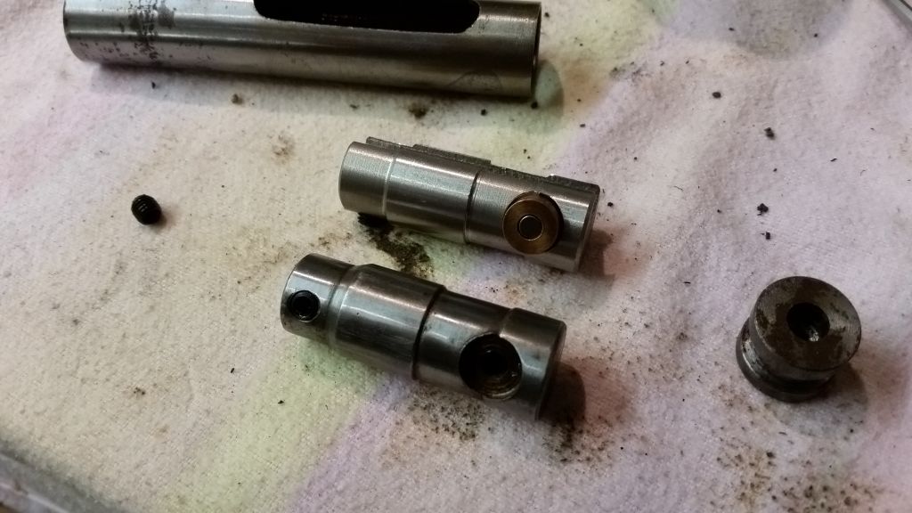
Almost done, as you can see I have added a slot and moved the grub screw 90 degrees so the offset for the pinch hole for the end of the throttle cable wont interfere with the brake cable.
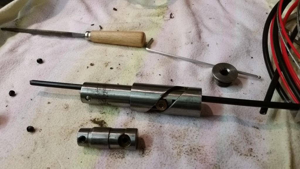
It’s running nice and smooth even with the cable running through it, should be able to finish it tomorrow, I’ll report back then.
Few more pictures to add, first one shows the new end plate, this retains the end of the throttle cable but allows the front brake to go straight through, it all look’s like I’ve made it on the wonk but I was trying to keep the throttle as close to the middle and the brake as close to the side.
Chop, chop… off goes the now spare part of the handlebar!
Bit of a problem as now the outside of the assembly does not fit in the tube very well, it’s a bit sloppy, well very sloppy so I have made a collar to take up all the slack.
I needed a way to exit the cables in a tidy place, should have done this before I welded the handlebars to the risers, good job I only tacked it.
Next I needed to add something for the inverted lever to mount in to so I added some bar I hollowed out, thought I had better weld it in the lathe to keep it all straight, I used a rolling centre to hold it in place.
Dont look too bad assembled either, pretty tidy.
So this is both cables exiting the front of the handle bars , I think they look alright, one issue I may have is I am having to use a throttle sized cable for a front brake which is not ideal but a larger cable simply wont fit through the throttle assembly, I can have a full size clutch though so all is not lost, well other than the lack of front brakes….
Now waiting for the levers to turn up, I’ll report back!
Not a happy bunny…
Fitted the new shiny generator tonight to prepare for finally firing her up, we have a spark and I have checked the timing so we are good to go, quick check over the carb needed but not a big job, we can fire it up on wd40 straight down her throat.
I modified the original nut from the standard generator to fit the new ‘Sparx’ Unit and was awarded for my efforts with a little surprise, when you tighten the nut up the crank goes solid.. I’m a little far in to the build to be dealing with this kind of problem…GGRRRRR
Here’s what I found.
So as you can see there is something wrong, this amount of end float would be destructive so there’s only one thing for it, I’m going to buy another engine from India, they are really good and have electric start and….OK who am I kidding, you know me I’ll fix it, I have some really big hammers…!
I didn’t enjoy ripping it apart again although I’m shocked how much crap was inside, all sorts of metal particles and guff, here it is in bits.
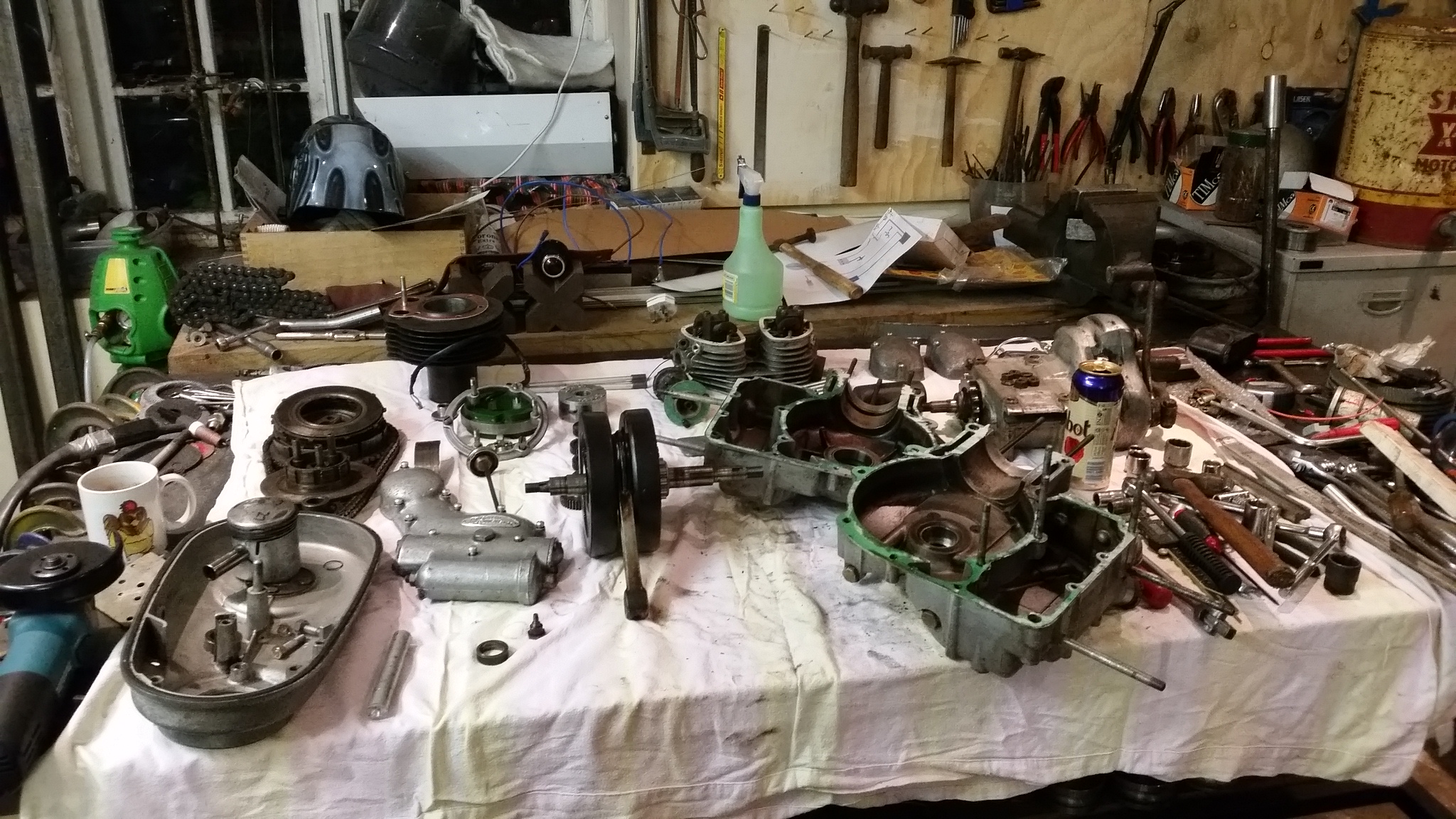
I’m really careful to organise parts so I don’t miss anything so I know everything I had was put back in the engine, the funny thing is that a spacer turned up the other week just after Mac visited, I’m not trying to point fingers at ‘captain Sabotage’ but we know he is very capable of underhanded tactics, I thought we were friends but it just goes to show you can’t trust anyone, my only action is to write a strongly worded letter to Scotland yard to demand JUSTICE.
Still waiting on the reply from Scotland yard, I know they must be busy so I’ll just sit tight, might try writing to Shaw Taylor, I doubt he’s doing much these days.
So tonight I started putting it all back together again, turns out the ‘returned’ spacer was a little worn, got the crank cases back together and still had play to the tune of 50 thou (1.2mm) so still to sloppy, I made a new spacer to the right size and tried again… it’s now a good fit, no side play at all so I’ve bolted the 2 cases together and fitted the timing wheels to now find out I have no idea how the points ignition aligns it’s self, I presumed it would just work but thinking about it i now need to figure this out.
No pictures tonight I’m afraid as my phone is out of battery so you will have to imagine a very bare engine sat on some wooded block perched on my bench, looking very sorry for it’s self but with no play in the crank!
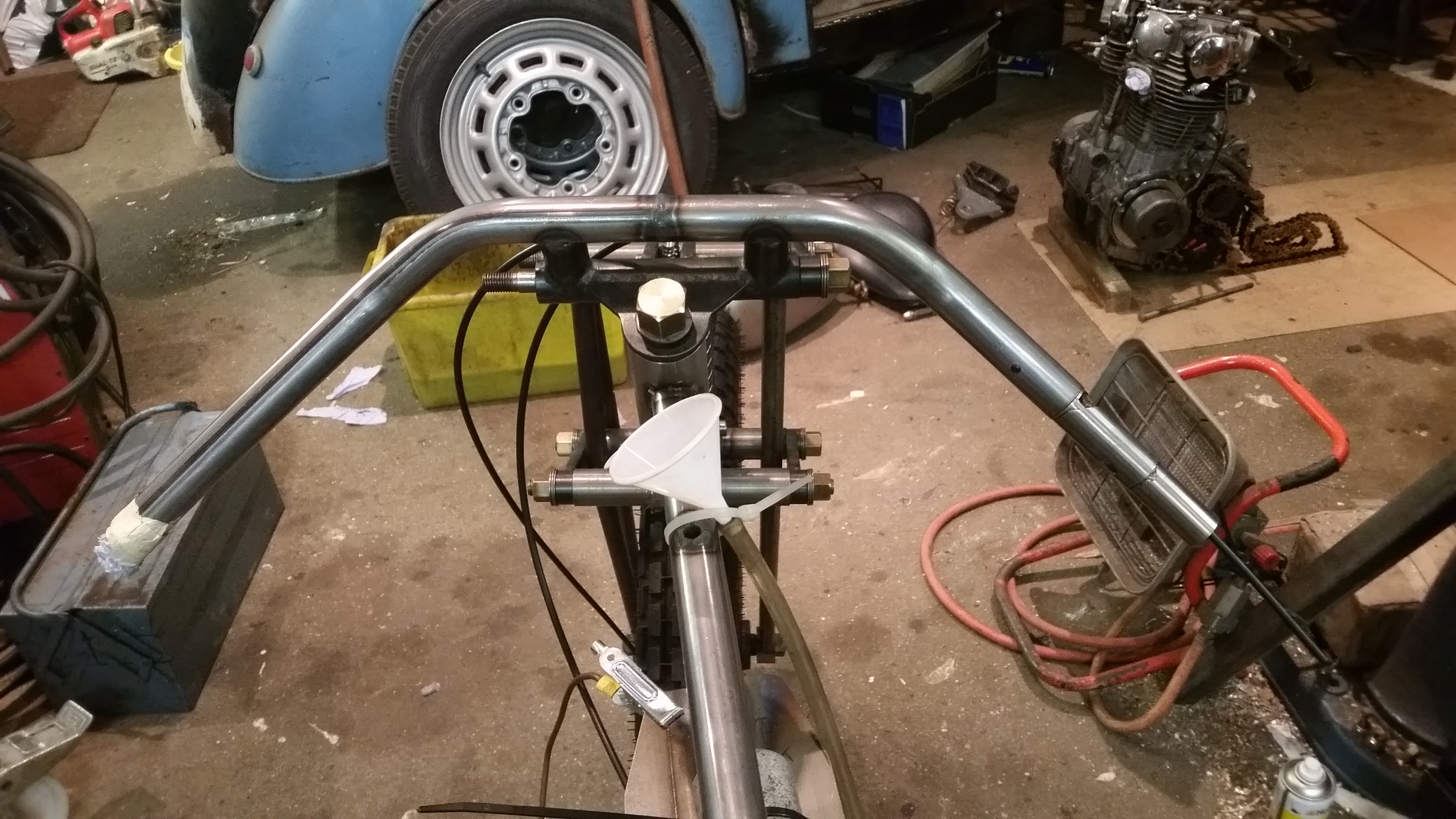
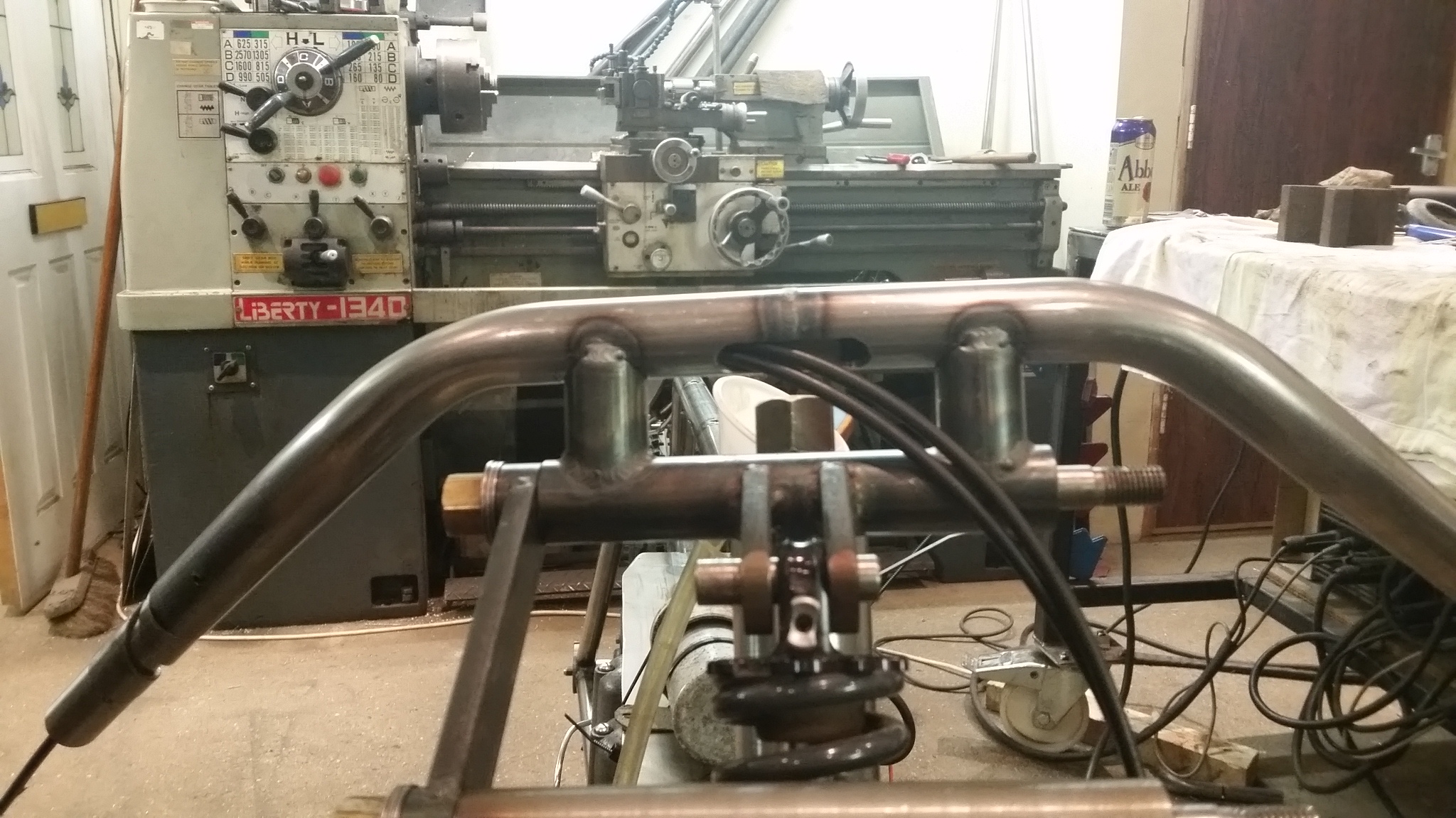
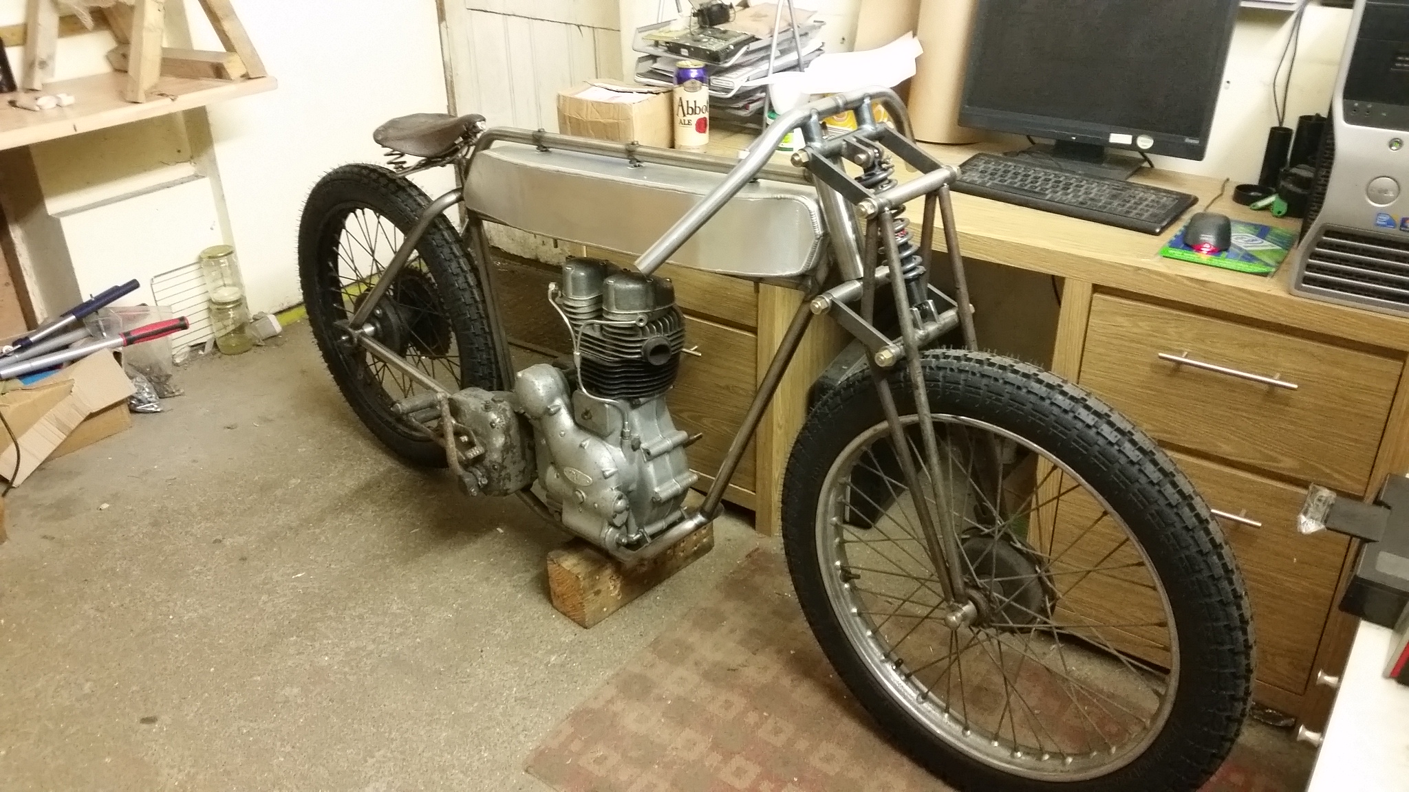
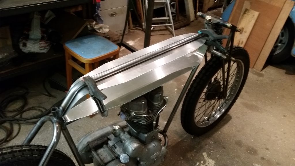
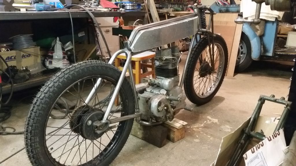
Right, now we know this contraption is definitely going to be a board track racer and not some shandy swilling gentleman’s velocipede we can add another important component, the handlebars, nice and short, swept down and kept simple to withstand the tremendous forces that will be thrust upon them when I unleash the full ‘SEVENTEEN’ horsepower and rely on the structural integrity when I thrash this beast as speeds over ‘FIFTY MILES PER HOUR’, we need to get these right or I am ‘TOAST’.
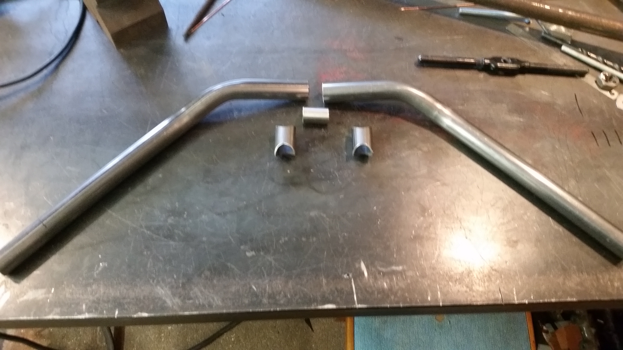
I had a good look on Google images to check out some styles and found that keep it simple looks good so I started bending some tubes and offering them up to the bike until I got an angle that looks right, made a little stub to go inside both tubes and a couple of standoff tubes to mount the handlebars, I went for the fixed position rather than adjustable to keep the appearance trim, I quite like it!
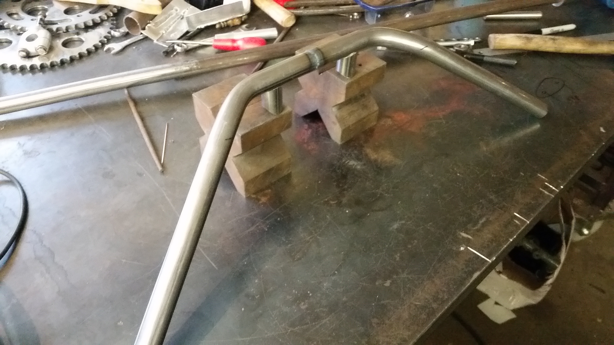
Welded it all up with my tig and the use of a couple of vee blocks, looks like I got it pretty straight.
Next I welded the bars to the top of the girders in the ‘full race’ position, I can imagine my thinner self laid over the tank ready to race, enjoying breathtaking acceleration up to fifty mph much quicker than most mopeds and bicycles.
I’m not planning on racing any mopeds just incase my calculations are wrong but in theory I should be able to beat them.
I have some grips on the way from China in the style of Coke bottles so I now need to decide on levers.
So it’s decided, it’s now going to be a board track racer, was going to be a ‘Gentlemans bike’ but as macs ‘Arley is looking sooo tasty we need to pull out the stops.
The main difference as I see it is Gentlemans motorcycles have comfortable handlebars to sit you in a distinguished position astride your propelled velocipede, board track racers lean you over your finely tuned machine in the racing position, this position cannot be rushed as your wedding tackle must be arranged correctly to avoid watering of the eyes, even before this machine has reached it’s first shake down ride I already am quite careful to mount corectly due to an experience I wont share…
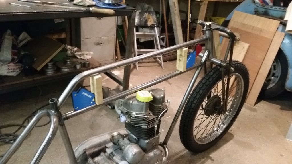
Now to build the petrol tank, this is my first so may not be the right way to do it but hey ho..
I needed to decide how high the gap would be to fit this contraption in so I used wood and magnets as I had these in front of me.
Now to work out the shape, I had a good look on google images to find a period shape and got the cardboard out and started cutting, very Blue Peter!
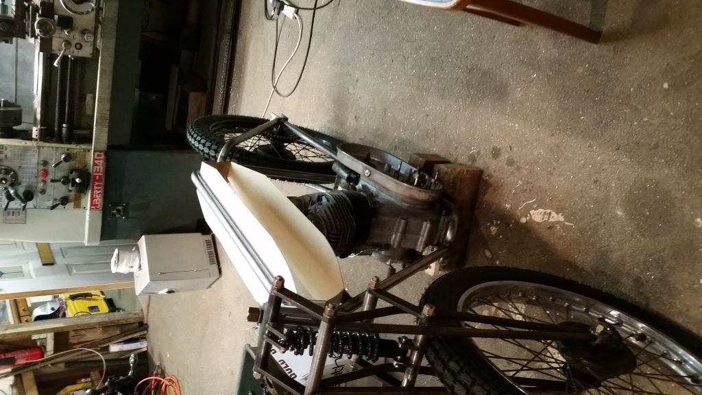
Got a shape I was happy with and transfered it to ‘Luminum..
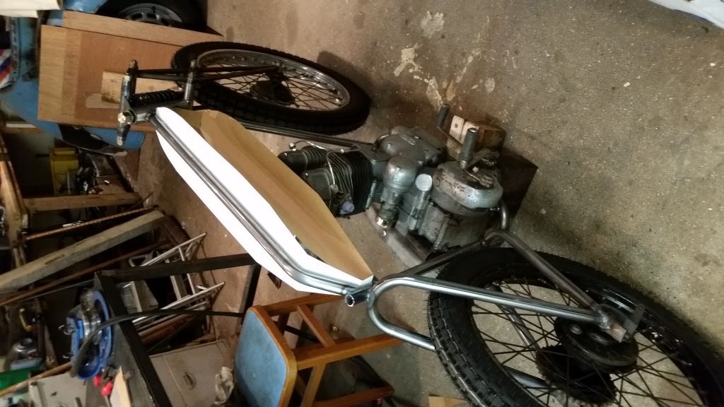
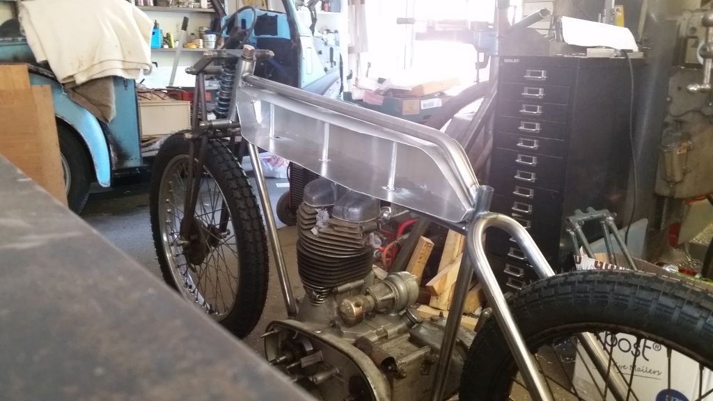
The great thing is at this point you can just sit on the bike with an angle grinder with a flap wheel and just sculpt it to look just how you want it. I made the bends using a precision bending machine, I certainly diddn’t bend them over an old fire extinguisher using my knee..! Ok so I did, you dont need bending equipment, just use what you have but tell people you have fancy equipment.
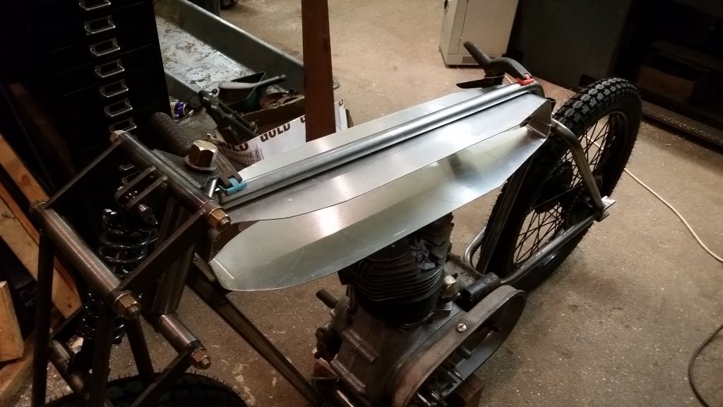
Traditionaly the tank is mounted using crappy mounts that look like conduit clips, I’m not keen so I came up with a plan, mount it using tubes that go all the way through the tank, what could go wrong…!
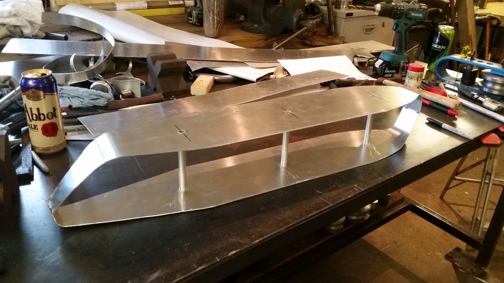
Easy peasy lemon squeasy so far but now we need some sides, break out some engineering cardboard once again.
Just lay on a piece of cardboard too big, mark it out with a sharpie and trim to size.
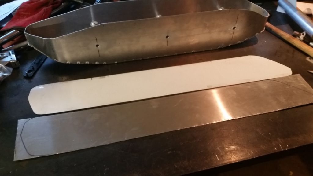
Transfer to aluminium sheet and trim with sheers.
Add some tack welds to hold it all in place, dont whatever you do weld up one side as it will distort more than you can imagine.
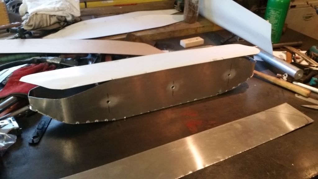
Starting to take shape, time to add the second side.
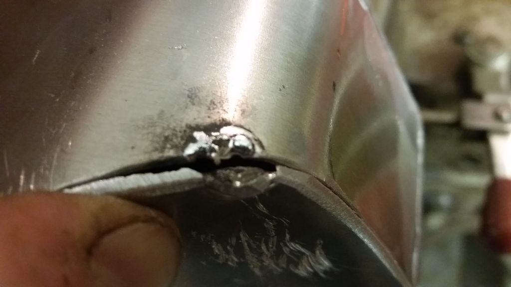
OK, so you can’t add the second side without somewhere for the heat to go or the weld just blows back at you and makes a mess, lesson learned..
Cut a hole for the filler to allow the heat to escape, works wonders!
Once you are happy with the fit and shape you can seam weld it up and make a platform for the tank to sit on.
I made up a leather gasket to hopfully reduce vibration.
Time to make the mounting rods, I welded a drill in the end of a 8mm rod so I could drill at a distance, it was a bit of a wobbly process but it worked well.
Don’t look too bad, it’s mounted quite secure and it looks alright, fairly happy with how this came out, next time I make one I will use thicker sheet as 1.5mm is just a bit tricky to weld.
No I’m not going to paint it, just a pin stripe the same colour as the frame, Burgandy red.


